Sealed type double-acting single-piston-rod hydraulic cylinder
A single-piston rod, double-acting technology, applied in the field of hydraulic cylinders, can solve problems such as cylinder overheating, metal heat attenuation, hydraulic rod and cylinder collision, etc., to reduce impact force and prevent overheating
- Summary
- Abstract
- Description
- Claims
- Application Information
AI Technical Summary
Problems solved by technology
Method used
Image

Examples
Embodiment Construction
[0024] The following will clearly and completely describe the technical solutions in the embodiments of the present invention with reference to the accompanying drawings in the embodiments of the present invention. Obviously, the described embodiments are only some, not all, embodiments of the present invention. Based on the embodiments of the present invention, all other embodiments obtained by persons of ordinary skill in the art without making creative efforts belong to the protection scope of the present invention.
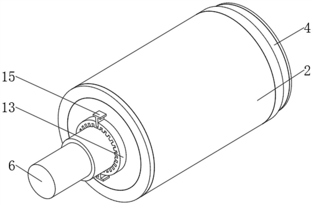
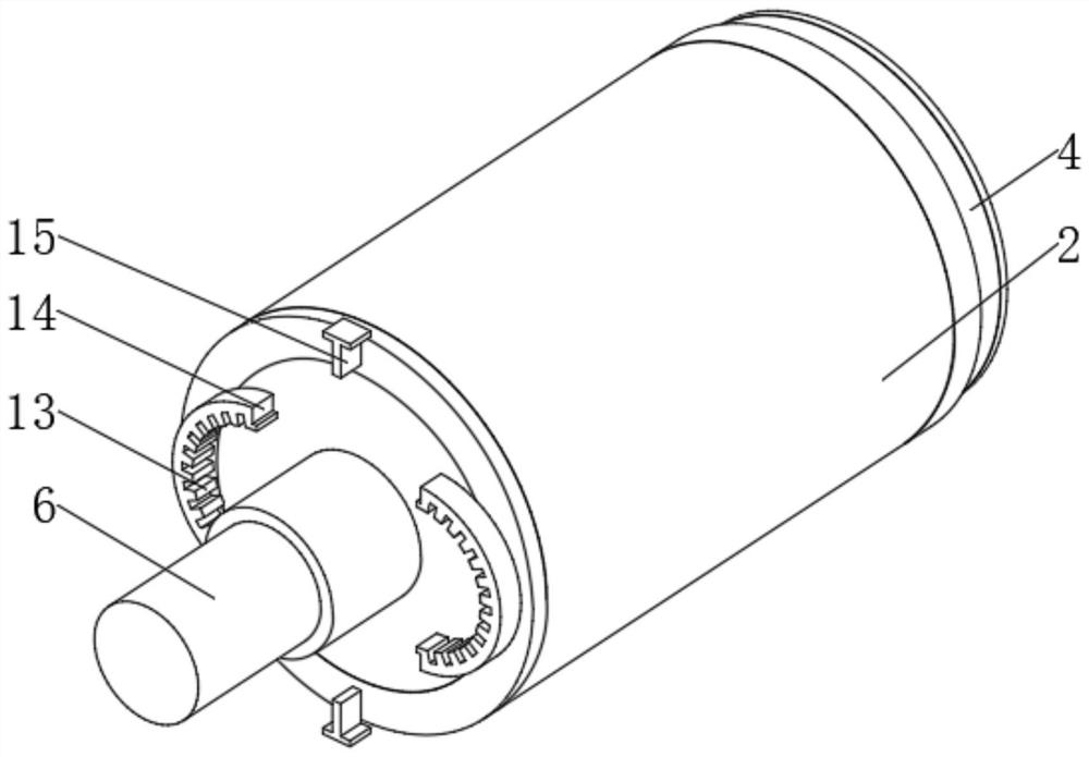
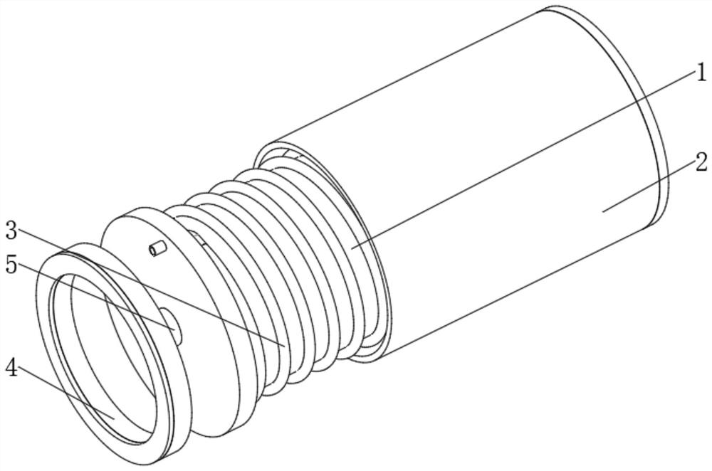
[0025] see Figure 1-5 , a sealed double-acting single-piston rod hydraulic cylinder, including a cylinder body 1, a limit groove 8 is provided on the inner surface of the cylinder body 1 at an equal angle, a movable block 11 is movably socketed inside the cylinder body 1, and the outer surface of the movable block 11 The limit block 12 is fixedly installed at an equal angle, the movable block 11 is movably clamped with the limit groove 8 through the limit blo...
PUM
 Abstract
Description
Claims
Application Information
 - R&D
- Intellectual Property
- Life Sciences
- Materials
- Tech Scout
- Unparalleled Data Quality
- Higher Quality Content
- 60% Fewer Hallucinations
Browse by: Latest US Patents, China's latest patents, Technical Efficacy Thesaurus, Application Domain, Technology Topic, Popular Technical Reports.
© 2025 PatSnap. All rights reserved.Legal|Privacy policy|Modern Slavery Act Transparency Statement|Sitemap|About US| Contact US: help@patsnap.com