
Aluminum alloy plate flatness detection device capable of marking unqualified parts

A technology for aluminum alloy plate and flatness detection, which is applied in the direction of mechanical roughness/irregularity measurement, and can solve problems such as inability to detect aluminum alloy plates

Pending Publication Date: 2021-05-28
陈辉
View PDF9 Cites 0 Cited by
  • Summary
  • Abstract
  • Description
  • Claims
  • Application Information

AI Technical Summary

Problems solved by technology

[0004] The purpose of the present invention is to provide a flatness detection device for aluminum alloy plates that can be used for batch level detection of aluminum alloy plates, and is suitable for marking unqualified parts of aluminum alloy plates with different thickness specifications, so as to solve the problem that cannot be solved in the above-mentioned background technology. The problem of testing aluminum alloy plates in batches

Method used


Image

  • Aluminum alloy plate flatness detection device capable of marking unqualified parts
  • Aluminum alloy plate flatness detection device capable of marking unqualified parts
  • Aluminum alloy plate flatness detection device capable of marking unqualified parts

Examples


Embodiment 1

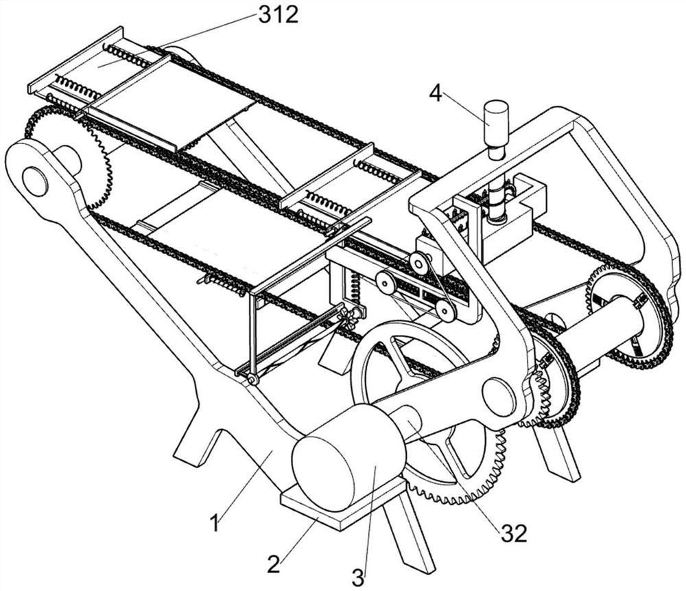
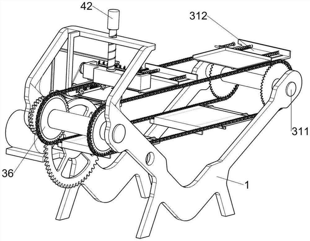
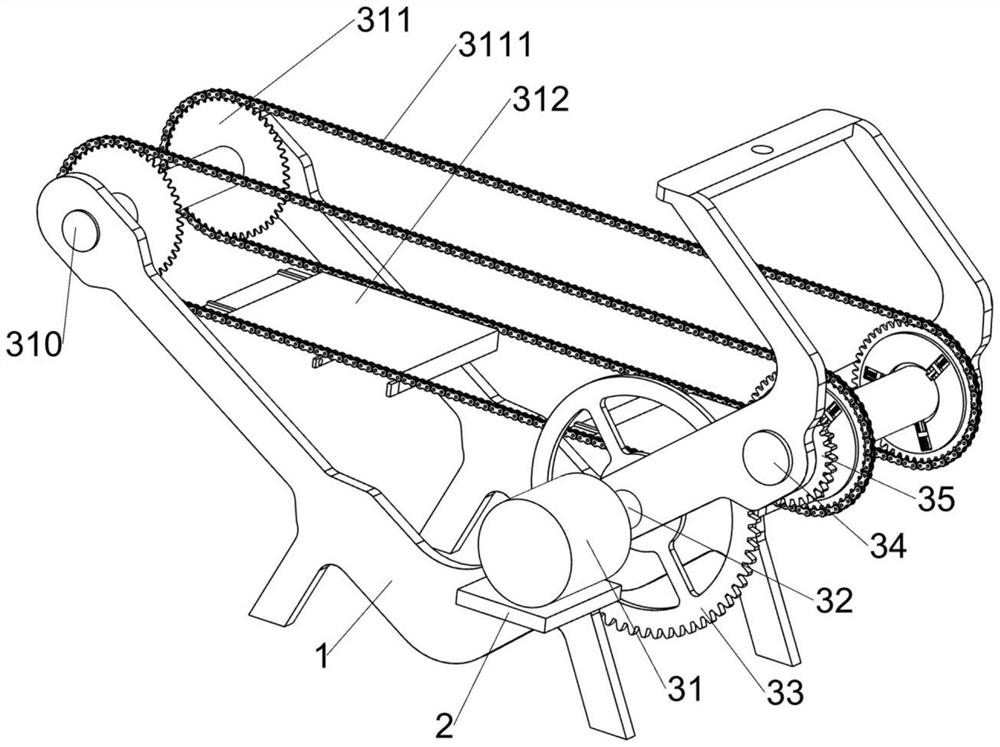
[0026] An aluminum alloy plate flatness detection device that can mark unqualified parts, such as Figure 1-9 As shown, it includes a bracket 1, a support plate 2, a clamping transmission assembly 3, an adjustment assembly 4 and a detection and recording assembly 5. The supporting plate 2 is fixedly installed on one side of the bracket 1, and the clamping transmission assembly 3 is rotatably connected to the bracket 1. , the adjustment component 4 is connected to the bracket 1 by means of screw connection, the adjustment component 4 is used to adjust the position of the detection plate 43 and the device on it, the detection and recording component 5 is arranged on the bracket 1, and the detection and recording component 5 is used for the aluminum alloy. board for inspection records.

[0027] The clamping transmission assembly 3 includes a motor 31, a power shaft 32, a sector gear 33, a clamping rod 1 34, a transmission gear 35, a sprocket 1 36, a sliding block 1 37, a clamping...

Embodiment 2

[0034] On the basis of Example 1, as Figure 8-9 As shown, it includes a toggle assembly 6, the detection and recording assembly 5 is slidably connected with a toggle assembly 6, and the toggle assembly 6 includes a push rod 61, a compression spring 62, a descending plate 63, a tension spring 64, and a fixed guide plate 65 , rotating ring 66 and pinion 67, a push rod 61 is slidably connected to the sliding placing plate 313, the pushing rod 61 is used to push the descending plate 63, and a compression spring 62 is connected between the pushing rod 61 and the sliding placing plate 313, and the descending The plate 63 is slidably connected to the fixed groove plate 51 away from the bracket 1, a tension spring 64 is connected between the fixed groove plate 51 and the descending plate 63, and the fixed guide plate 65 is fixed to the lower part of the descending plate 63 away from the fixed groove plate 51, close to the lower part of the descending plate 63. A rotating ring 66 is r...


PUM


Abstract

The invention relates to an aluminum alloy plate flatness detection device, in particular to an aluminum alloy plate flatness detection device capable of marking unqualified parts. The device comprises a bracket, a supporting plate, a clamping transmission assembly, an adjusting assembly and the like; the supporting plate is fixedly installed on one side of the support, the clamping transmission assembly is rotationally connected to the support, and the adjusting assembly is connected to the support in a threaded connection mode. A detection recording assembly and a chain drive a rotating gear and devices on the rotating gear to rotate, so that a belt wheel drives a second rotating shaft and a bevel gear to rotate through a belt, the bevel gear rotates to drive a detection gear to rotate, a toothed belt and devices on the toothed belt rotate, and a recording pen moves to detect an aluminum alloy plate.

Description

technical field [0001] The invention relates to an aluminum alloy plate leveling detection device, in particular to an aluminum alloy plate leveling detection device that can mark unqualified parts. Background technique [0002] Aluminum alloy plate is a kind of industrial building material. It is used in various industries according to different materials. It is widely used in aircraft structures, rivets, missile components, truck wheel hubs, packaging and thermal insulation aluminum foil, heat exchangers, bulkheads, wing ribs, wing spars, etc. In the industry, aluminum alloy plates are often used in high-precision occasions. After the aluminum alloy plates are processed, the flatness of the aluminum alloy plates needs to be tested. If the flatness is unqualified, it is difficult to meet the needs of downstream industries. [0003] The current flatness test of aluminum alloy plates cannot test aluminum alloy plates in batches. Usually, only a batch of samples are sampled. S...

Claims


Application Information

Patent Timeline
IPC IPC(8): G01B5/28
CPCG01B5/28
Inventor 陈辉
Owner 陈辉
Learn More