Multi-station detection device based on automatic control

An automatic control and detection device technology, which is applied in the direction of measuring devices, measuring device casings, measuring electronics, etc., can solve problems such as low efficiency, easy to generate errors, and prone to deviations in clamping positions, and achieve high efficiency and improve detection accuracy. Effect

Inactive Publication Date: 2021-05-28
张雪梅
View PDF1 Cites 8 Cited by
  • Summary
  • Abstract
  • Description
  • Claims
  • Application Information

AI Technical Summary

Problems solved by technology

[0005] In order to solve the above-mentioned technical problems, the present invention provides a multi-station detection device based on automatic control to solve the problem that when the multi-station turntable in the existing multi-station detection device is rotating, the servo motor or other angles are generally controlled by the controller. The motor drives the multi-station turntable to achieve angular rotation, but because the servo motor or other angular motors rotate in one direction for a long time, it is easy to generate errors, and once an error occurs, it will affect the detection of the detection parts on the multi-station detection device accuracy, thereby greatly reducing the reliability of the multi-station detection device, and when the existing multi-station detection device clamps and fixes the workpiece, it is necessary to manually place the workpiece on the fixture and then pass it through the fixture Clamping, the entire operation process is not only inefficient, but also prone to deviations in the clamping position, which greatly reduces the detection accuracy of the detection parts on the multi-station detection device

Method used


Image

  • Multi-station detection device based on automatic control
  • Multi-station detection device based on automatic control
  • Multi-station detection device based on automatic control

Examples


Embodiment

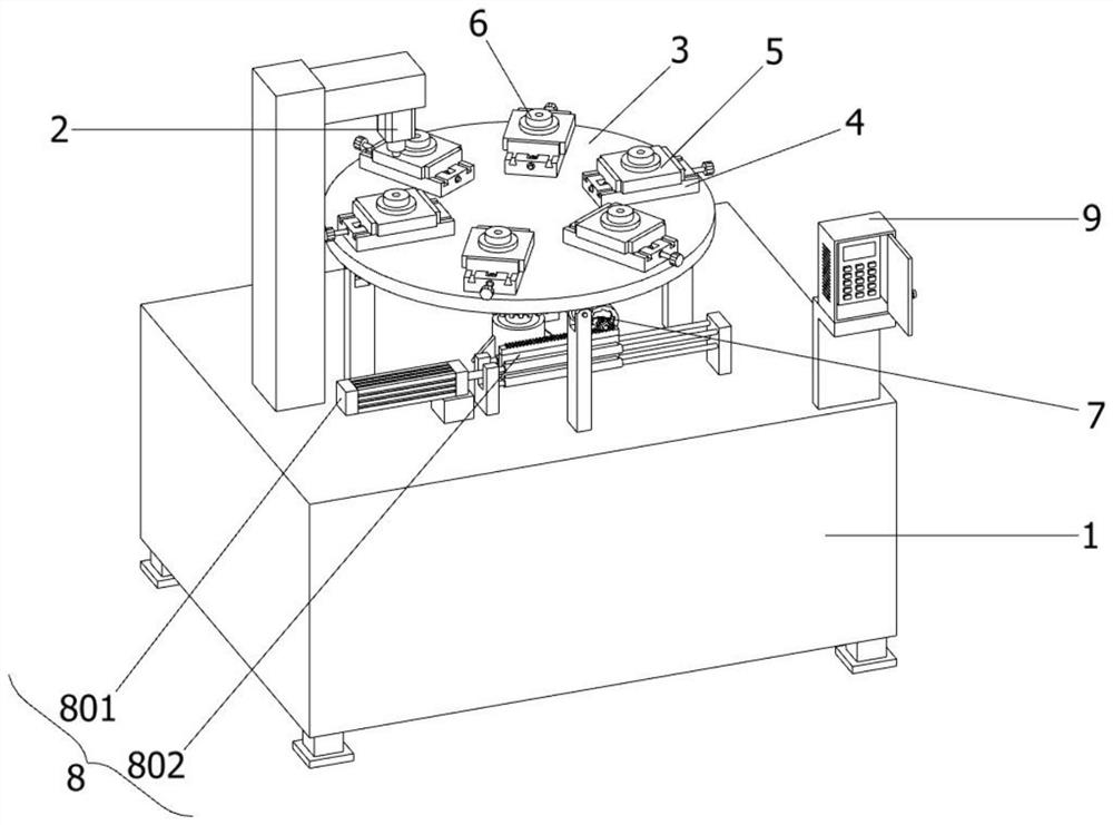
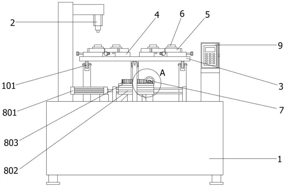
[0030] as attached figure 1 To attach Figure 8 Shown:

[0031] The present invention provides a multi-station detection device based on automatic control, which includes: a workbench 1, a detection piece 2 is installed on the upper left side of the workbench 1 through a pillar, the workbench 1 includes supporting rollers 101, and the upper end surface of the workbench 1 passes through The roller bracket is equipped with six support rollers 101, and the six support rollers 101 are distributed in a circular array on the upper part of the workbench 1; the upper middle side of the workbench 1 is provided with a multi-station turntable 3; the multi-station turntable 3 includes a support bushing 301 and worm gear 302, a rotating shaft is provided at the center of the bottom end surface of the multi-station turntable 3, and the lower end of the outer peripheral surface of the rotating shaft is rotatably connected with a support sleeve 301 fixed at the center of the upper end surfac...


PUM


Abstract

The invention provides a multi-station detection device based on automatic control, belongs to the technical field of detection devices, and aims to solve the problem that errors are easy to generate after a servo motor or other angle motors rotate in one direction for a long time when a multi-station turntable in the existing multi-station detection device rotates. The device comprises a workbench. The upper part of the left side of the workbench is provided with a detection member through a pillar, and the middle side of the upper part of the workbench is provided with a multi-station turntable. The multi-station rotating disc comprises a supporting shaft sleeve and a worm wheel, and a rotating shaft is arranged in the center of the bottom end face of the multi-station rotating disc. After the worm rotates three circles anticlockwise, because the transmission ratio between the worm and the worm gear is 18: 1, the worm gear drives the multi-station turntable to rotate one sixth circle, namely 60 degrees, so that the rotation angle of the multi-station turntable does not generate errors, the detection precision of a detection piece on the multi-station detection device is not influenced, and the reliability of the multi-station detection device in use is greatly improved.

Description

technical field [0001] The invention belongs to the technical field of detection devices, and more specifically relates to a multi-station detection device based on automatic control. Background technique [0002] There are semi-automatic and full automation in automation control. Automation control is a kind of integrated control technology and theory of mechanical and electrical automation in the production fields such as modern industry, agriculture, and manufacturing. Automation control technology is widely used in industry, agriculture, military, scientific research, transportation, commerce, medical care, service and family, etc. The use of automatic control can not only liberate people from heavy physical labor, some mental work, and harsh and dangerous working environments, but also expand human organ functions, greatly improve labor productivity, and enhance human ability to understand and transform the world. . [0003] For example, application number: CN20171084...

Claims


Application Information

Patent Timeline
Patent Type & Authority Applications(China)
IPC IPC(8): G01D21/00G01R31/01G01R1/04B65G29/00
CPCB65G29/00G01D21/00G01R1/0425G01R31/01
Inventor 张雪梅
Owner 张雪梅
Why Eureka
Try Eureka