Deepwater sampling device for water conservancy projects

A sampling device and water conservancy engineering technology, applied in sampling devices and other directions, can solve the problems of sampling efficiency and low sampling accuracy, and achieve the effects of increasing stability, improving protection performance and avoiding offset.

Inactive Publication Date: 2021-05-28
高玉东
View PDF5 Cites 0 Cited by
  • Summary
  • Abstract
  • Description
  • Claims
  • Application Information

AI Technical Summary

Problems solved by technology

[0006] Aiming at the deficiencies of the prior art, the present invention provides a deep-water sampling device for hydraulic engineering, which solves the problem that current deep-water riverbed mud sampling equipment cannot accurately know whether the sampler is completely inserted into the mud, which affects the sampling efficiency. It is easy to mix different layers of silt in deep water, which causes the problem of low accuracy of sampling samples

Method used


Image

  • Deepwater sampling device for water conservancy projects
  • Deepwater sampling device for water conservancy projects
  • Deepwater sampling device for water conservancy projects

Examples


Embodiment 1

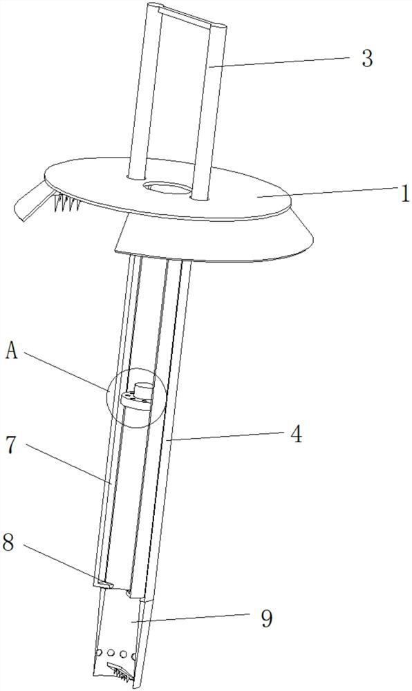
[0032] Such as Figure 1-3 As shown, the present invention provides a technical solution: a deep-water sampling device for water conservancy projects, including a movable roof 1, and movable slots 2 are arranged on both sides of the movable roof 1 near the middle position, and the inside of the movable slot 2 runs through and slides Connected with a limit bracket 3, the position of the limit bracket 3 located below the movable top plate 1 is fixedly connected with a sampling limit frame 4, the top of the sampling limit frame 4 penetrates and is slidably connected with a driving insert rod 5, and the top of the drive insert rod 5 is connected to the movable top plate 1 fixedly connected, the two sides of the sampling limit frame 4 are symmetrically provided with an adjustable sampling mechanism 7, the bottom end of the joint sampling mechanism 7 is fixedly connected with a cutting partition 8, and the cutting partition 8 extends to the inside of the sampling limit frame 4, The ...

Embodiment 2

[0038] Such as Figure 4 As shown, on the basis of Embodiment 1, the present invention provides a technical solution: a deep-water sampling device for hydraulic engineering. The top of the sampling limit frame 4 is provided with a driving inner cavity 18, and the driving insertion rod 5 is located in the driving inner cavity 18. One end inside is fixedly connected with a transmission ramp 19 .

[0039] A sampling movable plate 20 runs through and is slidably connected to the lateral position inside the driving inner cavity 18 , and one end of the sampling movable plate 20 located inside the driving inner cavity 18 is fixedly connected to a driving cone plate 21 .

[0040]One end of the sampling movable plate 20 located outside the drive inner cavity 18 is fixedly connected with a magnetic spatula 22 , and the internal inclined surface of the driving cone plate 21 is uniformly provided with shaking grooves 23 . Ensure the stability of sampling sludge and improve sampling effic...

Embodiment 3

[0042] Such as Figure 5 As shown, on the basis of Embodiment 1 and Embodiment 2, the present invention provides a technical solution: a deep water sampling device for hydraulic engineering. A liquid discharge hole 92 is evenly arranged near the lower position, and the bottom end of the insertion cone 91 is rotatably connected with a contact scraper 93 , and the bottom of the contact scraper 93 has a surface evenly fixedly connected with a catch hook 94 . Prevent impurities from entering the sampling equipment and improve the accuracy of sampling samples.

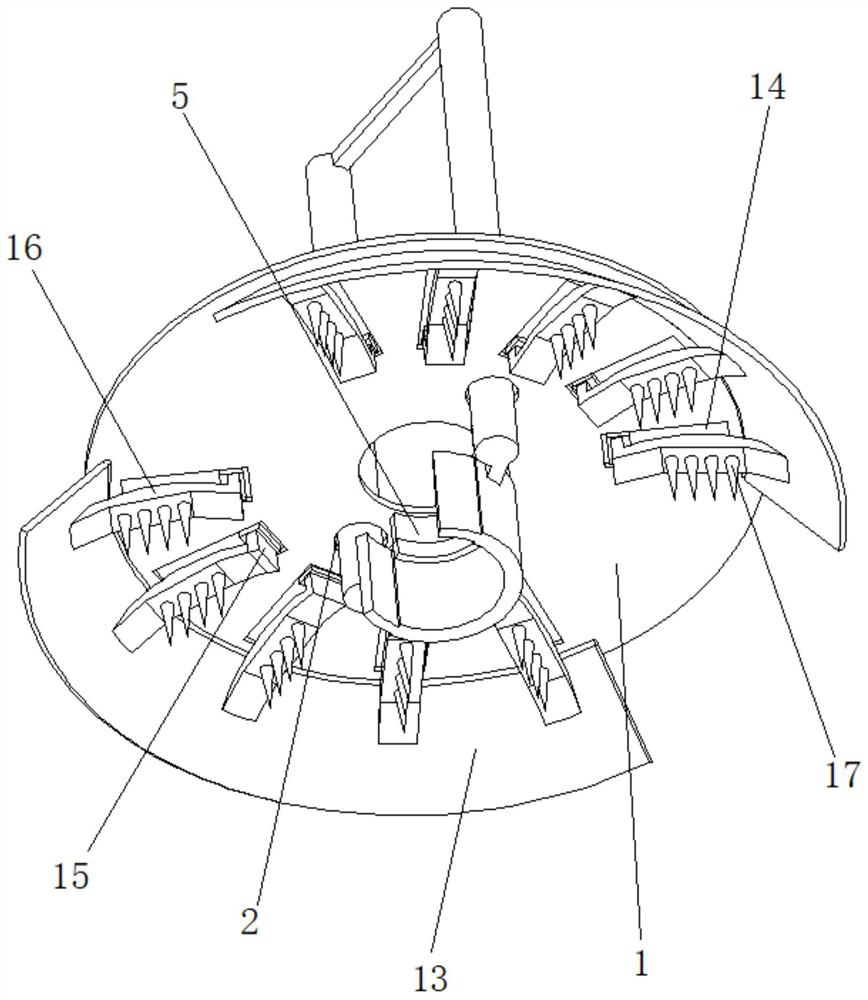
[0043] Working principle: Insert the sampling limit frame 4 vertically into the underwater position to be sampled, fix the limit bracket 3 with the external driver, gradually insert the sampling limit frame 4 into the mud in deep water, and the limit protection plate 13 is formed by contacting the top of the mud The circular cover ensures that the silt at the position to be sampled will not be washed away by the water flow...


PUM


Abstract

The invention discloses a deepwater sampling device for water conservancy projects, wherein the deepwater sampling device comprises a movable top plate; movable insertion grooves are formed in the two sides, close to the middle position, of the movable top plate; a limiting support penetrates through the interiors of the movable insertion grooves and is slidably connected with the movable insertion grooves, and a sampling limiting frame is fixedly connected to the position, located below the movable top plate, of the limiting support; a driving insertion rod penetrates through and is slidably connected to the top end of the interior of the sampling limiting frame, the top of the driving insertion rod is fixedly connected with the movable top plate, adjusting sampling mechanisms are symmetrically arranged on the two sides of the sampling limiting frame, and slitting partition plates are fixedly connected to the bottom ends of the adjusting sampling mechanisms and extend to the inner side of the sampling limiting frame; and the bottom end of the sampling limiting frame is fixedly connected with a shoveling driving mechanism. The invention relates to the technical field of water conservancy projects. According to the deepwater sampling device for the water conservancy projects, the stability during sampling is improved, and deviation during sampling is avoided.

Description

technical field [0001] The invention relates to the technical field of hydraulic engineering, in particular to a deep water sampling device for hydraulic engineering. Background technique [0002] Water conservancy projects are projects built to control and allocate natural surface water and groundwater to achieve the purpose of eliminating harm and rejuvenating profits. Also known as water engineering. Water is an indispensable precious resource for human production and life, but its natural state does not fully meet human needs. [0003] For example, the Chinese invention publication number is: a kind of water conservancy and water quality sampling device of CN109883760A, comprising a hanging ring, a semicircle upper cover, a sample cylinder, a water stop clamp, a rubber hose, a movable base plate, a conical counterweight, a mounting frame, a water temperature gauge, The scale gauge, deflector, and hanging ring are installed in the installation hole of the deflector thro...

Claims


Application Information

Patent Timeline
Patent Type & Authority Applications(China)
IPC IPC(8): G01N1/14
CPCG01N1/14
Inventor 高玉东
Owner 高玉东
Why Eureka
Try Eureka