
A low-voltage scr device for esd protection

An ESD protection and device technology, used in semiconductor devices, electrical solid devices, electrical components, etc., can solve the problems of sudden increase in leakage current, inability to achieve low power consumption, etc., to achieve low leakage current, avoid PNPN collusion phenomenon, low power consumption consumption effect

Active Publication Date: 2022-08-02
UNIV OF ELECTRONICS SCI & TECH OF CHINA
View PDF10 Cites 0 Cited by
  • Summary
  • Abstract
  • Description
  • Claims
  • Application Information

AI Technical Summary

Problems solved by technology

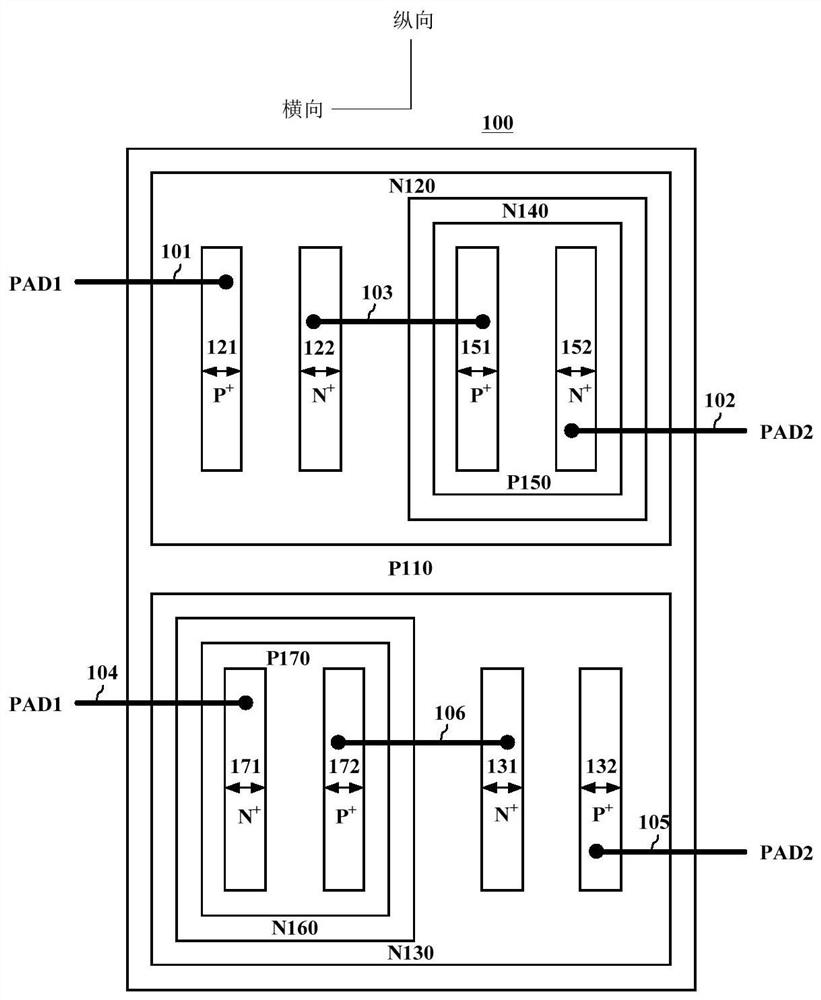
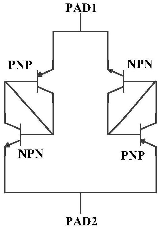
However, the inventors of the present invention found in the follow-up scientific research work that there is a potential PNPN collusion phenomenon in the low-power bidirectional SCR device structure of this structure, which leads to the leakage current of the low-power bidirectional SCR device structure when the working voltage is 1.5V The sharp increase makes the device unable to achieve low power consumption when the operating voltage is above 1.5V, such as Figure 9 shown

Method used


Image

  • A low-voltage scr device for esd protection
  • A low-voltage scr device for esd protection
  • A low-voltage scr device for esd protection

Examples


Embodiment 1

[0024] This embodiment provides a low-voltage unidirectional SCR device 300 for ESD protection, the schematic top view of which is as follows Figure 4 As shown, the schematic cross-sectional view along the line A-A' is as follows Figure 7 shown; the low-voltage unidirectional SCR device has an anode and a cathode, the anode is electrically connected to PAD1, and the cathode is electrically connected to PAD2; it will specifically include:

[0025] The P-type substrate 210 , the N-type deep buried layer 220 formed on the P-type substrate 210 , the first N-type deep well region, the first P-type deep well region formed on the deep buried layer 220 and adjacent from left to right in order a well region 260, a second N-type deep well region 240, a second P-type deep well region 250, and a third N-type deep well region;

[0026]The second N-type deep well region 240 is provided with a first P-type heavily doped active region 241 and a first N-type heavily doped active region 242 ...

Embodiment 2

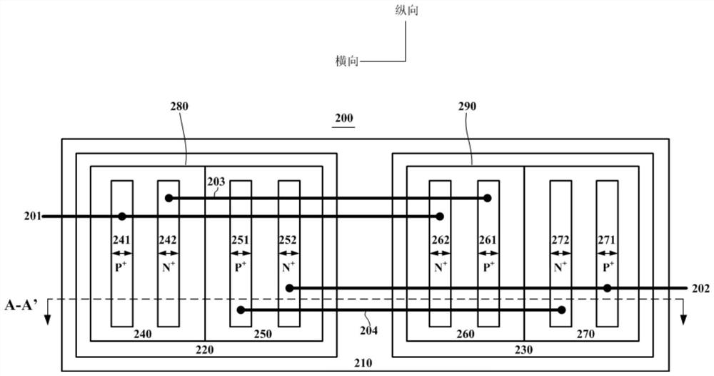
[0028] This embodiment provides a low-voltage bidirectional SCR device 200 for ESD protection, the schematic top view of which is as follows Figure 5 As shown, the schematic cross-sectional view along the line A-A' is as follows Figure 7 As shown, the schematic cross-sectional view along the B-B' line is as follows Figure 8 As shown, it specifically includes: a first SCR device and a second SCR device arranged in the longitudinal direction, wherein the first SCR device and the second SCR device have the same structure as the unidirectional SCR device 300 in Embodiment 1, but only in the lateral direction. The first SCR device and the second SCR device are placed in opposite directions; more specifically, in this embodiment, the first SCR device is placed in the same direction as the unidirectional SCR device 300 in Embodiment 1, and its anode is the same as the PAD1 Electrical connection, the cathode is electrically connected to PAD2, the second SCR device is placed in the...


PUM


Abstract

The invention belongs to the technical field of electrostatic protection, and provides a low-voltage one-way / two-way SCR device for ESD protection; ) contains 3 N+ / P‑WELL diodes, which further enhances the DC blocking capability of the device, resulting in lower leakage current, lower static power consumption, and more stable parasitic capacitance values ​​than traditional ESD protection devices. Better electrostatic protection effect; compared with the existing low-power bidirectional SCR devices for ESD protection, the present invention adopts a novel structure design to avoid the potential PNPN cross-connection phenomenon in the device structure, so that the low-voltage bidirectional SCR device has an operating voltage of 1.5 There is no sudden increase in leakage current at V, that is, the device of the present invention can still achieve effective ESD protection with lower power consumption when the operating voltage is above 1.5V and below 1.8V.

Description

technical field [0001] The invention belongs to the technical field of electrostatic protection, and in particular relates to a low-voltage unidirectional and bidirectional SCR device for ESD protection. Background technique [0002] With the continuous development of integrated circuit technology, the chip damage caused by Electro-Static Discharge (ESD) events is becoming more and more serious, which seriously restricts the reliability of semiconductor products; ) ESD protection design is very necessary; and, on the whole, the more advanced the manufacturing process, the more difficult the ESD protection project is. [0003] Among the many optional ESD protection devices, SCR (Silicon-Controlled-Rectifier, silicon controlled rectifier) ​​has a very high area efficiency and is widely used. In the low-voltage field, the direct-connected SCR (DCSCR, directly-connected SCR) is widely used, and its traditional bidirectional structure such as figure 1 As shown, its equivalent c...

Claims


Application Information

Patent Timeline
Patent Type & Authority Patents(China)
IPC IPC(8): H01L27/02
CPCH01L27/0262
Inventor 刘志伟卿乙宏张钰鑫李洁翎杜飞波
Owner UNIV OF ELECTRONICS SCI & TECH OF CHINA
Learn More