
Visible light projectile shooting target device

A visible light and target technology, applied in the field of shooting training, can solve problems such as failure, reflection interference, bullet kinetic energy exceeding the standard, etc., and achieve the effects of shortened launch time, strong anti-interference, and low manufacturing cost

Active Publication Date: 2022-03-25
RESEARCH INSTITUTE OF TSINGHUA UNIVERSITY IN SHENZHEN
View PDF0 Cites 1 Cited by
  • Summary
  • Abstract
  • Description
  • Claims
  • Application Information

AI Technical Summary

Problems solved by technology

[0002] At present, due to the problem of excessive bullet kinetic energy, live ammunition shooting violates relevant domestic laws and regulations, so it cannot be widely used in folk entertainment and shooting confrontation activities
The traditional infrared laser simulation shooting technology is unable to carry out precise aiming and shooting because the emitted light is invisible and the infrared reflection interference is serious.
At present, the simulated shooting and shooting technology based on visible light emission is generally judged by light intensity judgment reception or image recognition without using coding, which is easily affected by ambient light; in the case of using coding, each simulation The duration of the fired "light bullet" will be longer. Due to the existence of shooting jitter, a continuous light will be formed at the beginning of the target, and it will not be possible to achieve accurate shooting simulation with only one impact point when the bullet hits the target.
At the same time, in various shooting competitions, the size and shape of the target positions are different. The existing simulated target shooting system is very inconvenient to use and requires special customization.

Method used


Image

  • Visible light projectile shooting target device
  • Visible light projectile shooting target device
  • Visible light projectile shooting target device

Examples


Embodiment Construction

[0082] The following will clearly and completely describe the technical solutions in the embodiments of the present invention with reference to the accompanying drawings in the embodiments of the present invention. Obviously, the described embodiments are only some of the embodiments of the present invention, not all of them. Based on the embodiments of the present invention, all other embodiments obtained by persons of ordinary skill in the art without making creative efforts belong to the protection scope of the present invention.

[0083] It should be noted that when an element is considered to be "connected" to another element, it may be directly connected to the other element or there may be an intervening element at the same time. When an element is referred to as being "disposed on" another element, it can be directly disposed on the other element or intervening elements may also be present.

[0084] Unless otherwise defined, all technical and scientific terms used here...


PUM


Abstract

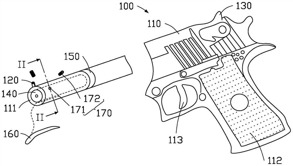
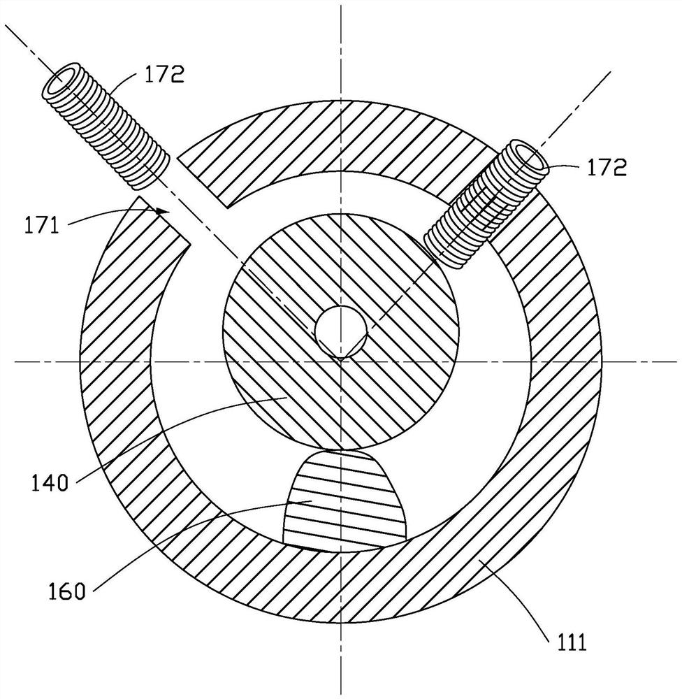
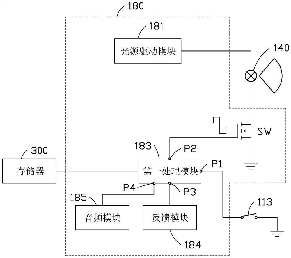
The invention discloses a visible light projectile shooting target device, which includes a shooting unit and a receiving target unit. The shooting unit includes a casing and a light emitter, wherein the light emitter is arranged at the exit end of the casing, and the light emitter emits visible light. bomb; the receiving target unit includes a plurality of receiving targets that can be fixedly spliced, wherein, the target body of each receiving target is a light-transmitting material, and its edge and bottom are opaque materials; each target body is connected There is a photosensitive sensor, and the photosensitive sensor receives the visible light bomb emitted by the light emitter. The visible light projectile shooting and shooting device provided by the present invention can use the mechanical collimator to aim and shoot with the human eye, has strong anti-interference ability, and can achieve accurate shooting in various strong and weak ambient light situations, and the shape and size of the target can be freely according to needs Combination, with strong practicality.

Description

technical field [0001] The invention relates to the technical field of shooting training, in particular to a visible light bullet shooting target device. Background technique [0002] At present, due to the problem of excessive bullet kinetic energy, live ammunition shooting violates relevant domestic laws and regulations, so it cannot be widely used in folk entertainment and shooting confrontation activities. The traditional infrared laser simulation shooting technology is unable to perform accurate aiming and shooting because the emitted light is invisible and the infrared reflection interference is serious. At present, the simulated shooting and shooting technology based on visible light emission is generally judged by light intensity judgment reception or image recognition without using coding, which is easily affected by ambient light; in the case of using coding, each simulation The duration of the fired "light bullet" will be longer. Due to the existence of shooting ...

Claims


Application Information

Patent Timeline
Patent Type & Authority Patents(China)
IPC IPC(8): A63B69/00A63B71/06
CPCA63B69/00A63B71/0622A63B2071/063A63B2225/50
Inventor 郭文秀宋健蒋小涛
Owner RESEARCH INSTITUTE OF TSINGHUA UNIVERSITY IN SHENZHEN
Learn More