Supercharge Your Innovation With Domain-Expert AI Agents!

Portable automatic vacuum test bench

A vacuum test and portable technology, which is applied in portable laboratories, laboratory stools/lab tables, laboratory appliances, etc., can solve the problems of inconvenient and portable installation methods, and achieve the effect of improving convenience

Pending Publication Date: 2021-06-01
美科仪器仪表校准技术服务(无锡)有限公司
View PDF0 Cites 0 Cited by
  • Summary
  • Abstract
  • Description
  • Claims
  • Application Information

AI Technical Summary

Problems solved by technology

[0005] The invention provides a portable automatic vacuum test bench, which solves the problem that the fixed installation method of the automatic vacuum test bench is inconvenient to carry

Method used


Image

  • Portable automatic vacuum test bench
  • Portable automatic vacuum test bench
  • Portable automatic vacuum test bench

Examples


no. 1 example

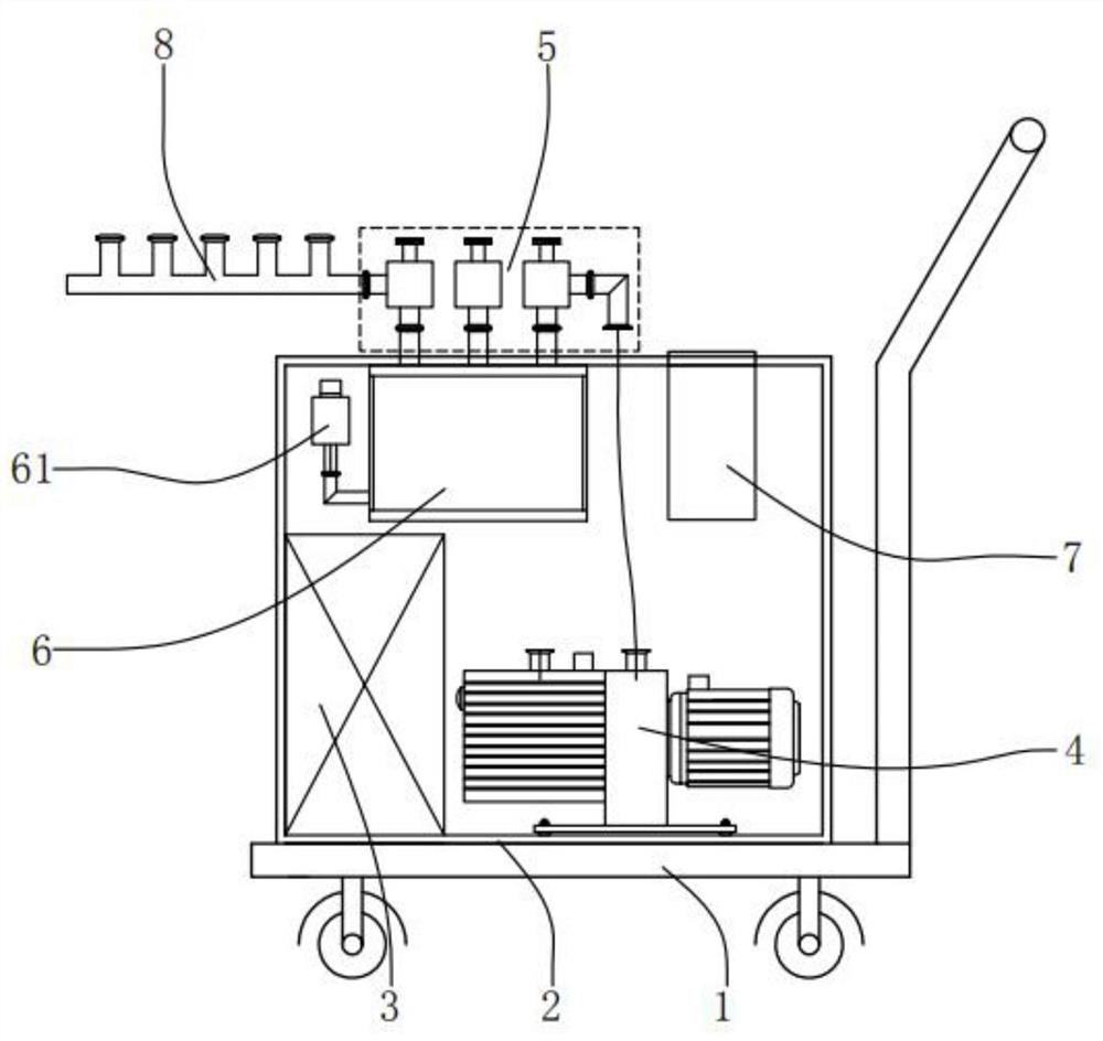
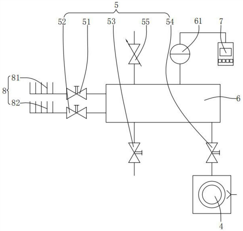
[0030] Please refer to figure 1 , figure 2 and image 3 ,in, figure 1 The structural representation of the first embodiment of the portable automatic vacuum test bench provided by the present invention; figure 2 for figure 1 The system diagram of the portable automated vacuum test bench shown; image 3 for figure 1 Overall exterior view shown. A portable automatic vacuum test bench includes: a trolley 1; a mounting frame 2, the bottom of which is fixed on the top of the trolley 1; a tool locker 3, the tool locker 3 is arranged on the The inner side of the mounting frame 2; the vacuum pump 4, the bottom of the vacuum pump 4 is fixed on the bottom of the inner wall of the mounting frame 2; the valve group 5, the valve group 5 is arranged on the top of the mounting frame 2, the valve Group 5 includes a first manual valve 51, a second manual valve 52, a third manual valve 53, a fourth manual valve 54 and a fine-tuning valve 55; a vacuum buffer chamber 6, the surface of wh...

no. 2 example

[0047] see Figure 4 , Figure 5 , Figure 6 , Figure 7 and Figure 8 , based on the portable automated vacuum test bench provided in the first embodiment of the present application, the second embodiment of the present application proposes another portable automated vacuum test bench. The second embodiment is only a preferred mode of the first embodiment, and the implementation of the second embodiment will not affect the independent implementation of the first embodiment.

[0048] Specifically, the difference of the portable automated vacuum test bench provided in the second embodiment of the present application is that the portable automated vacuum test bench also includes: the bottom of the mounting frame 2 is provided with universal wheels 21, and the mounting frame The outer surface of 2 is respectively provided with a power control panel 22, a vacuum gauge control panel 23 and a molecular pump control panel 24, the top of the inner wall of the mounting frame 2 is f...


PUM

PropertyMeasurementUnit
Diameteraaaaaaaaaa
Lengthaaaaaaaaaa

Abstract

The invention provides a portable automatic vacuum test bench, which comprises: a cart; a mounting frame, wherein the bottom of the mounting frame is fixed to the top of the cart; and a tool storage cabinet arranged on the inner side of the mounting frame. The portable automatic vacuum test bench provided by the invention has the advantages that the whole equipment can be conveniently moved, adjusted and transported, the situation that the equipment is inconvenient to move and adjust the position due to a fixed structure is avoided, the tool storage cabinet is arranged on one side of the mounting frame and is used for storing detachable parts so as to prevent the detachable parts from moving and occupying space when the automatic vacuum test bench is moved, so that the convenience of moving and adjusting the vacuum test bench is improved; and the fine adjustment valve is arranged on the vacuum buffer chamber, and performs fine adjusting by using a micrometer, so that the problem that a vacuum balance port reserved in a cavity of a conventional valve cannot be accurately controlled due to vacuum pressure is solved, and the purposes that vacuum pumping of a vacuum pump and gas entering the cavity are balanced are achieved.

Description

technical field [0001] The invention relates to the technical field of vacuum automatic test equipment, in particular to a portable automatic vacuum test bench. Background technique [0002] As one of the important equipment in vacuum test, the vacuum test bench is too large and occupies a large area when used. In order to achieve the stability of use, the vacuum test bench is mostly fixed in one position and cannot be moved. [0003] The existing fixed vacuum test bench is inconvenient to carry and use after being fixed. The vacuum pump is difficult to achieve the actual vacuum purpose and is difficult to control accurately to the Pa level, which brings inconvenience to the user's portability and movement, and increases the restrictions on the use of the vacuum test bench. [0004] Therefore, it is necessary to provide a portable automatic vacuum test bench to solve the above technical problems. Contents of the invention [0005] The invention provides a portable automat...

Claims


Application Information

Patent Timeline
IPC IPC(8): B01L1/00B01L1/02B01L9/02
CPCB01L1/02B01L1/52B01L9/02B01L2300/14
Inventor 仲锡春
Owner 美科仪器仪表校准技术服务(无锡)有限公司
Features
  • R&D
  • Intellectual Property
  • Life Sciences
  • Materials
  • Tech Scout
  • Unparalleled Data Quality
  • Higher Quality Content
  • 60% Fewer Hallucinations
Learn More