
Automatic feeding, cutting and shaping system

An automatic feeding and silo technology, which is applied to other manufacturing equipment/tools, metal processing, manufacturing tools, etc., can solve the problems that automatic feeding and continuous automatic processing cannot be realized in the cutting of cans, so as to achieve good market returns and increase Processing production efficiency and the effect of solving hidden dangers

Pending Publication Date: 2021-06-01
王一晓
View PDF1 Cites 0 Cited by
  • Summary
  • Abstract
  • Description
  • Claims
  • Application Information

AI Technical Summary

Problems solved by technology

[0005] The present invention effectively solves the problem that automatic feeding and continuous automatic processing cannot be realized in the cutting of pop cans in the prior art by setting the feeding device, the No. 1 rotary device, the No. 2 rotary device, the No. 3 rotary device, the cutting mechanism and the shaping mechanism. The problem is that at the same time, the end of the cans that have been cut can be flattened and shaped, which is conducive to the smoothness of the recycled cans, greatly improving the processing efficiency and the quality of cans cutting and recycling, and is conducive to obtaining better market returns.

Method used


Image

  • Automatic feeding, cutting and shaping system
  • Automatic feeding, cutting and shaping system
  • Automatic feeding, cutting and shaping system

Examples


Embodiment 1

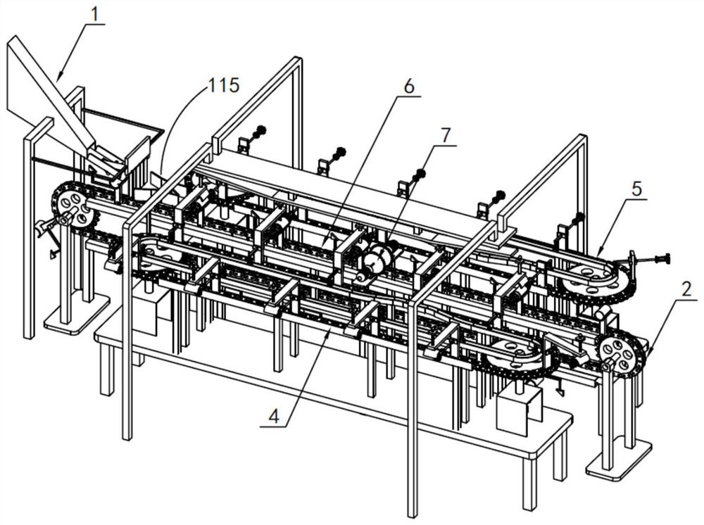
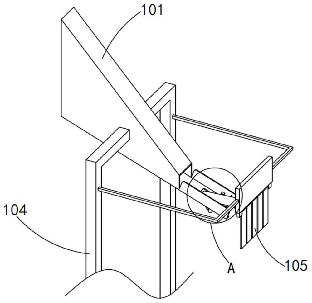
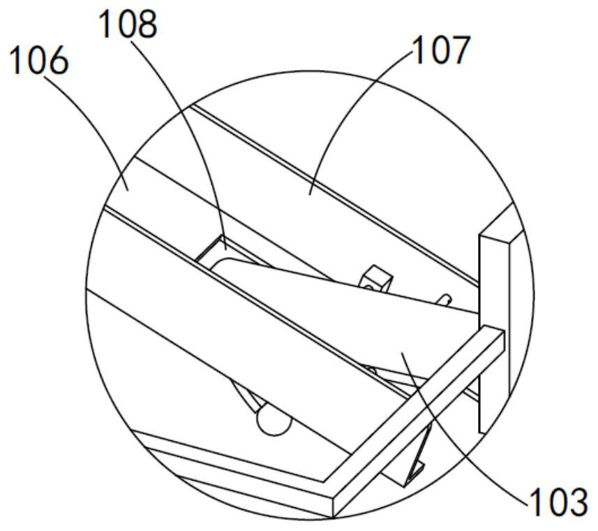
[0046] Such as Figure 1 to Figure 18 As shown, an automatic feeding cutting shaping system includes a feeding device 1, and the feeding device 1 includes a feeding bin 101, and the bottom of the feeding bin 101 is provided with a discharge channel 102, and the discharge channel 102 There is a material turning assembly 103 on the top, and a No. 1 rotary device 2 is provided below the feeding device 1. A number of equidistant bearing mechanisms 3 are arranged on the No. 1 rotary device 2. The carrier mechanism 3 includes a push Component 301 and a supporting component 302, the pushing component 301 is used to push the turning component 103 under the drive of the No. 1 rotary device 2 to transfer the pop-top cans output from the upper bin 101 to the supporting component 302 individually, The two sides of the moving path of the carrying mechanism 3 are respectively provided with a No. 2 turning device 4 and a No. 3 turning device 5. The No. 2 turning device 4 is provided with a n...


PUM


Abstract

The invention relates to an automatic feeding, cutting and shaping system which comprises a feeding device. The feeding device comprises a feeding bin; a discharging channel is arranged at the bottom of the feeding bin; a turning assembly is arranged on the discharging channel; a first rotating device is arranged below the feeding device; a bearing mechanism is arranged on the first rotating device, and comprises a pushing assembly and a supporting assembly; a second rotating device and a third rotating device are arranged on the two sides of the bearing mechanism respectively; a downward pressing mechanism is arranged on the second rotating device; a machining channel is formed among the first rotating device, the second rotating device and the third rotating device; a cutting mechanism is arranged in the machining channel; a left shaping mechanism is arranged on the second rotating device; a right shaping mechanism is arranged on the third rotating device; and the left shaping mechanism and the right shaping mechanism comprise expanding assemblies and advancing and retreating assemblies. According to the automatic feeding, cutting and shaping system provided by the invention, the problem that in the prior art, automatic feeding and automatic machining cannot be achieved during ring-pull can cutting is solved, end openings of the cut ring-pull cans can be shaped, and better market benefits can be obtained.

Description

technical field [0001] The invention relates to the technical field of recycling and processing of pop cans, in particular to an automatic feeding, cutting and shaping system. Background technique [0002] Pop cans have become a relatively common storage tool for beverages. When people drink their beverages, there will be a large number of pop cans left. Since pop cans are generally made of metal materials, such as aluminum, iron and other metals, they have a certain recycling value. Although the amount of cans used is large, the recycling rate is not high. Most of the discarded cans and unqualified products in the production process of cans are returned to the furnace after extrusion. In order to increase the value of discarded cans, they began to cut the cans. [0003] A Chinese invention patent with the publication number CN109954919A discloses that the present invention provides a can cutting device, including a base, a first sliding block, a clamping mechanism, a drivin...

Claims


Application Information

Patent Timeline
IPC IPC(8): B23P23/04B23Q7/14
CPCB23P23/04B23Q7/14
Inventor 王一晓
Owner 王一晓
Learn More