Adjusting and damping device and preparation method of high-damping alloy material
A vibration-damping device and vibration-damping pad technology are used in metal processing equipment, manufacturing tools, metal processing mechanical parts, etc., which can solve the problem of adjusting vibration-damping pads without the function of fine-tuning, and ensure dimensional accuracy and quality. Long service life and wide application range
- Summary
- Abstract
- Description
- Claims
- Application Information
AI Technical Summary
Problems solved by technology
Method used
Image
Examples
Embodiment 1
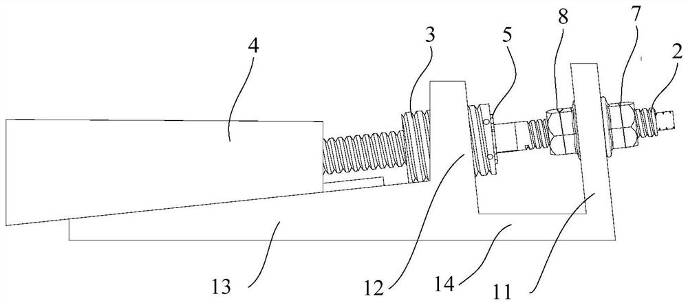
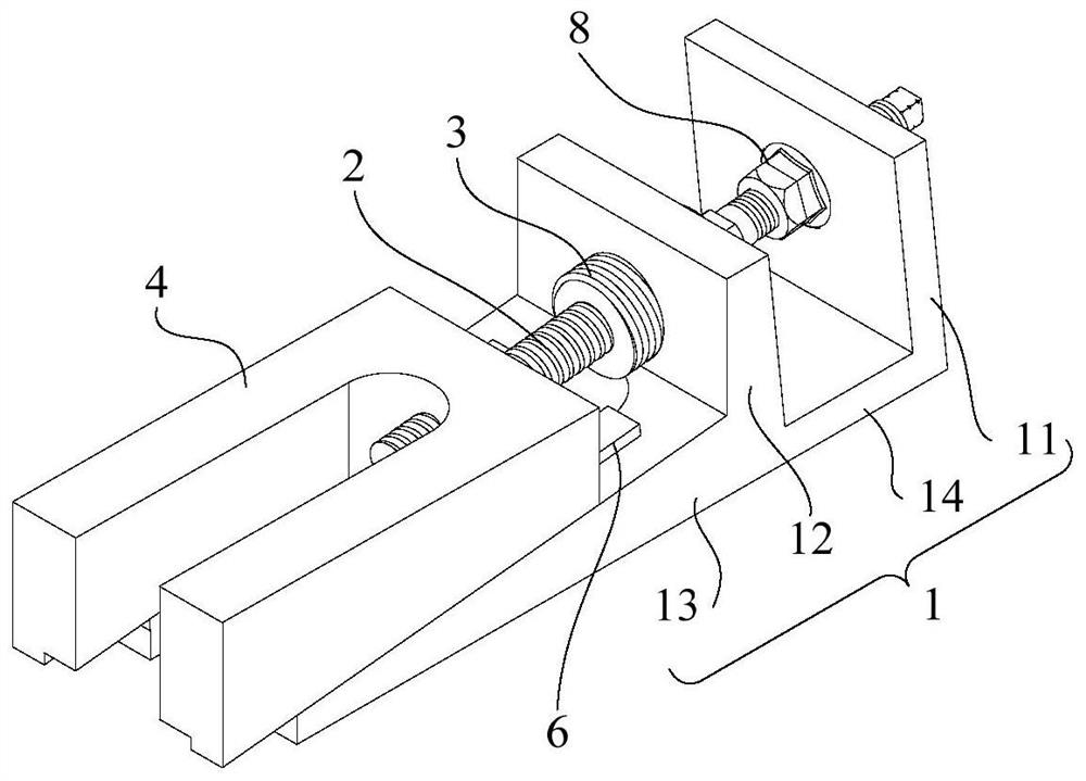
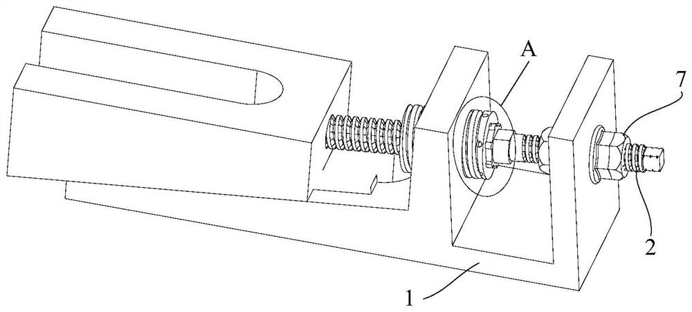
[0056] see Figure 1 to Figure 5 As shown, the embodiment of the present application provides an adjustable damping device, including: a first support member 1, a first adjustment member 2, a second adjustment member 3 and a second support member 4;
[0057] Wherein, the second adjusting member 3 is detachably passed through the first supporting member 1, and the second adjusting member 3 is screwed and rotatably connected with the first supporting member 1;
[0058] One end of the first adjustment member 2 extending out of the first support member 1 is rotatably connected to the second support member 4, and the second support member 4 can move relative to the first support member 1;
[0059] It can be seen that the rotation of the first adjustment member 2 or the rotation of the second adjustment member 3 can be converted into a linear motion of the second support member 4 relative to the first support member 1 through the above structural arrangement;
[0060] The first adj...
Embodiment 2
[0098] The adjusting damping device in this embodiment is an improvement on the basis of Embodiment 1. The technical content disclosed in Embodiment 1 will not be described repeatedly, and the content disclosed in Embodiment 1 also belongs to the content disclosed in this embodiment.
[0099] see Figure 7 with Figure 8 As shown, the general scheme of the second embodiment is the same as that of the first embodiment, the difference is that: the two surfaces where the third supporting part 13 and the second supporting member 4 are in contact are arranged in a horizontal plane, and the third supporting part 13 The surface away from the second support member 4 is set in a horizontal plane; the first support member 1 also includes a fourth support portion 15, and the fourth support portion 15 is arranged on an end of the third support portion 13 away from the second support portion 12; adjust The damping device also includes a third support member 9 arranged on the second suppor...
Embodiment 3
[0103] The adjusting damping device in this embodiment is an improvement on the basis of Embodiment 1. The technical content disclosed in Embodiment 1 will not be described repeatedly, and the content disclosed in Embodiment 1 also belongs to the content disclosed in this embodiment.
[0104] see Figure 9 to Figure 12 As shown, the general scheme of the third embodiment is the same as that of the first embodiment, the difference lies in:
[0105] The first support member 1 also includes a fourth support portion 15 and a fifth support portion 16, the fourth support portion 15 is connected to one side of the second support portion 12, and the fifth support portion 16 is connected to the opposite side of the second support portion 12. The other side is connected; the fourth support portion 15 and the fifth support portion 16 are also connected to the opposite two sides of the third support portion 13 respectively, and the fourth support portion 15 and the fifth support portion 1...
PUM
| Property | Measurement | Unit |
|---|---|---|
| Elastic modulus | aaaaa | aaaaa |
Abstract
Description
Claims
Application Information
 - R&D
- Intellectual Property
- Life Sciences
- Materials
- Tech Scout
- Unparalleled Data Quality
- Higher Quality Content
- 60% Fewer Hallucinations
Browse by: Latest US Patents, China's latest patents, Technical Efficacy Thesaurus, Application Domain, Technology Topic, Popular Technical Reports.
© 2025 PatSnap. All rights reserved.Legal|Privacy policy|Modern Slavery Act Transparency Statement|Sitemap|About US| Contact US: help@patsnap.com


