Concrete stirring device for constructional engineering

A technology for construction engineering and mixing devices, which is applied in the direction of cement mixing devices, clay preparation devices, cleaning methods and utensils, etc. It can solve the problems of single mixing method and poor finished products, and achieve the effect of preventing shaking, preventing sticking, and smooth up and down displacement

Pending Publication Date: 2021-06-01
龙凤
View PDF7 Cites 3 Cited by
  • Summary
  • Abstract
  • Description
  • Claims
  • Application Information

AI Technical Summary

Problems solved by technology

In traditional concrete mixing, the motor drives the rotating rod to drive the mixing column to mix the concrete in the box. The mixing method is single, and the finished product is poor.

Method used


Image

  • Concrete stirring device for constructional engineering
  • Concrete stirring device for constructional engineering
  • Concrete stirring device for constructional engineering

Examples


Embodiment 1

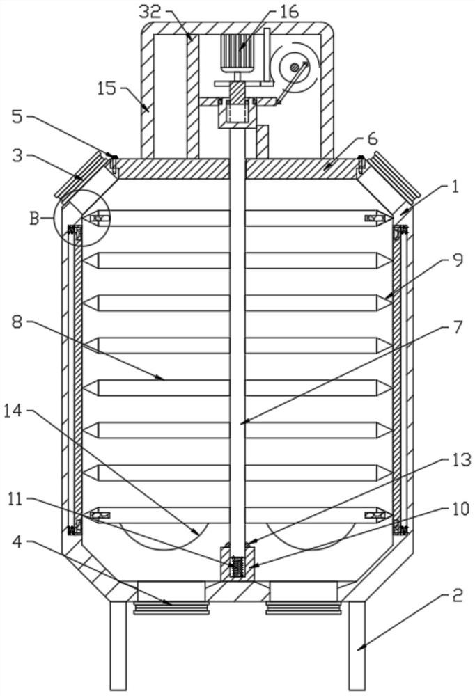
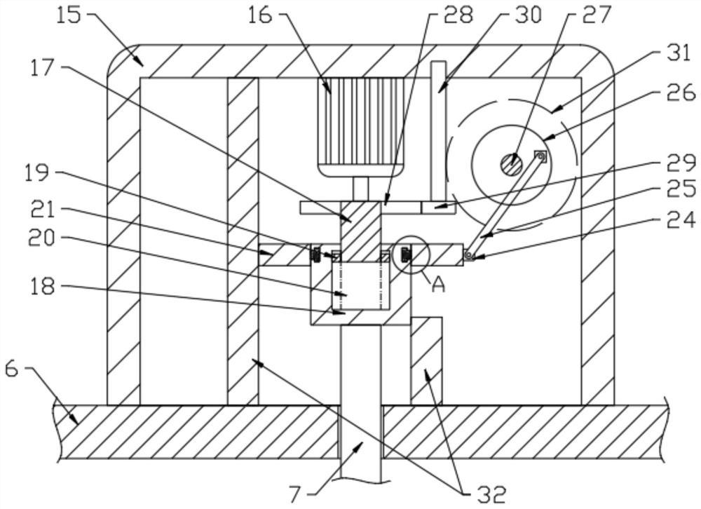
[0025] see Figure 1-5 , a concrete mixing device for construction engineering, comprising a box body 1 and a number of feed ports 3 arranged on the upper side of the box body 1, a number of discharge ports 4 and support columns 2 are provided at the lower end of the box body 1, and the upper end of the box body 1 passes through The connecting bolt 5 is connected with the box cover 6, and the rotating rod 7 is connected to the inside of the box body 1, and a number of stirring columns 8 are fixedly connected to the sides of the rotating bar 7. The casing 15 is provided with a rotating assembly that drives the rotating rod 7 to rotate. The casing 15 is provided with a displacement assembly that drives the rotating rod 7 to move up and down. The casing 15 is provided with a connecting assembly that drives the displacement assembly. The side wall of the casing 1 A moving cylinder 33 is provided, and a vibrating assembly for driving the moving cylinder 33 to vibrate is arranged in...

Embodiment 2

[0042] Further improvements are made on the basis of Embodiment 1, and the improvements are as follows: the lower end of the bottom stirring column 8 is fixedly connected with a briquetting block 14, and the cross-sectional profile of the briquetting block 14 is semicircular, and the bottom stirring column 8 follows the When the rotating rod 7 rotates and displaces up and down, the briquetting block 14 fixedly connected with the mixing column 8 displaces up and down, thereby making the concrete mixing effect on the lower side of the box body 1 better and the quality of the finished product is better.


PUM


Abstract

The invention discloses a concrete stirring device for constructional engineering. The concrete stirring device comprises box body feeding interfaces, a plurality of discharging interfaces and supporting columns arranged at the lower end of the box body, and a box cover is connected with the upper end of the box body through connecting bolts. A rotating rod, stirring columns and scraping blocks are arranged on the box body, a case arranged at the upper end of the box body, and a rotating assembly, a displacement assembly and a connecting assembly are arranged in the case. A moving cylinder is arranged on the side wall of the box body, and a vibration assembly is arranged in the box body. A motor drives a connecting column to rotate, so that a connecting cylinder rotates under the action of a clamping block and a sliding groove, then the rotating rod rotates, and the rotating rod rotates to stir concrete in the box body. A connecting column rotates to enable a driving gear to rotate, then the connecting cylinder and the rotating rod move up and down while rotating through a driven gear, a worm gear, a worm, a rotating disc, a long rod, a connecting block and other components, then the stirring columns move up and down while stirring is conducted, and concrete in the box body is effectively stirred.

Description

technical field [0001] The invention relates to the technical field of mixing, in particular to a concrete mixing device for construction engineering. Background technique [0002] Concrete mixer is a machine that mixes cement, sand and gravel aggregate and water and mixes it into concrete mixture. It is also an indispensable tool in the field of house construction, which brings great convenience to the construction process. In traditional concrete mixing, the motor drives the rotating rod to drive the mixing column to mix the concrete in the box. The mixing method is single, and the finished product is poor. Contents of the invention [0003] The object of the present invention is to provide a concrete mixing device for construction engineering, so as to solve the problems raised in the above-mentioned background technology. [0004] To achieve the above object, the present invention provides the following technical solutions: [0005] A concrete mixing device for const...

Claims


Application Information

Patent Timeline
Patent Type & Authority Applications(China)
IPC IPC(8): B28C5/16B28C5/48B28C5/08B08B9/087
CPCB28C5/16B28C5/485B28C5/0831B08B9/087
Inventor 龙凤
Owner 龙凤
Why Eureka
Try Eureka