
Brushless direct current motor controlled by servo system

A brush DC motor and servo system technology, applied in the field of servo systems, can solve the problems of surface rust vibration, connection end face gap, poor fixing effect, etc., and achieve the effect of avoiding screw rust

Inactive Publication Date: 2021-06-01
陈建国
View PDF0 Cites 0 Cited by
  • Summary
  • Abstract
  • Description
  • Claims
  • Application Information

AI Technical Summary

Problems solved by technology

[0003] Based on the inventor’s discovery above, the existing ones mainly have the following disadvantages. For example, when it is applied in a relatively humid area and installed in the open air, the bracket is placed horizontally at the bottom, and the connection is fixed by screws, which are affected by moisture. The screw connection of the end face is easy to rust, and the vibration will shake off the surface rust during the working process of the motor, which will cause a small gap on the connection end face, resulting in poor fixing effect and moisture will flow into the shell from the gap under wet conditions internal, causing internal damage

Method used


Image

  • Brushless direct current motor controlled by servo system
  • Brushless direct current motor controlled by servo system
  • Brushless direct current motor controlled by servo system

Examples


Embodiment 1

[0027]Appendfigure 1 AdherentFigure 5 Down:

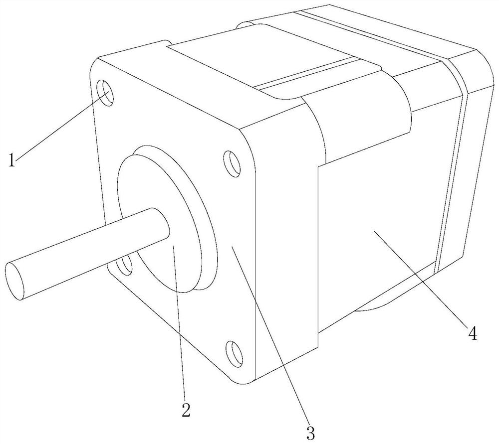
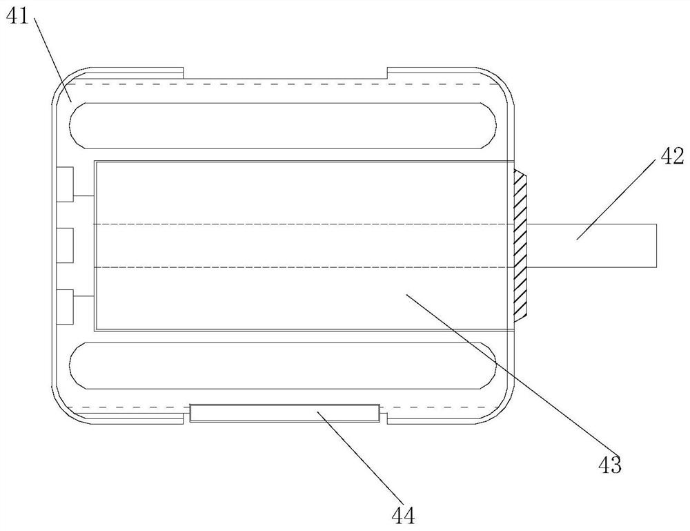
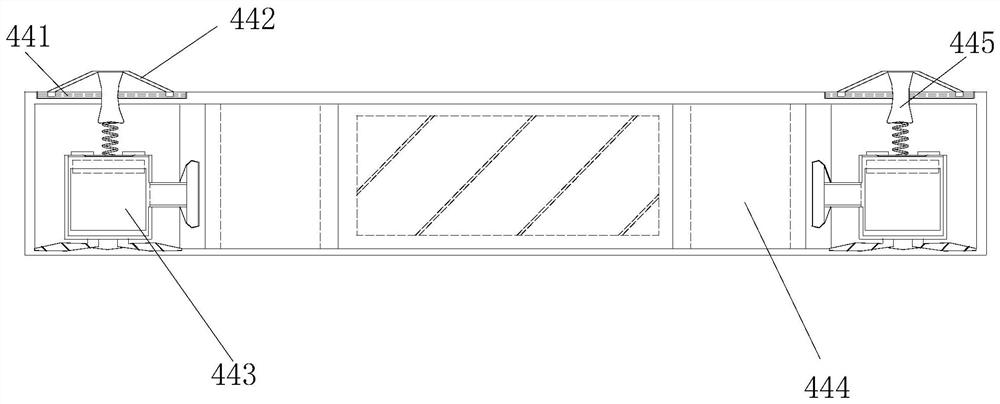
[0028]The present invention provides a brushless DC motor controlled by a servo system comprising a bolt hole 1, a fixing ring 2, a cover plate 3, a housing 4, and the bolt hole 1 and the cover plate 3 are integrated structures, the fixation The ring 2 outer ring is solidly coupled to the inner ring of the cover plate, the cover plate 3 acts on the end face of the housing 4, the fixing ring 2 located at the front end of the housing 4; the housing 4 is from the inner frame 41 The shaft 42, the permanent magnet 43, the mounting assembly 44, the rotating shaft 42 and the permanent magnet 43 as an integrated structure, the permanent magnet 43 active engage inside the inner frame 41, the mounting assembly 44 activity is engaged The middle portion of the frame 41 is located below the permanent magnet 43.

[0029]Wherein, the mounting assembly 44 is composed of a slide rail 441, a control rod 442, a rustting device 443, a mounting hole 444, and a low...

Embodiment 2

[0035]AppendFigure 6 AdherentFigure 8Down:

[0036]Wherein, the communication tube 332 is composed of inner groove 321, a rear plate 322, a discharge plate 323, and the inner groove 321 is embedded on the right end surface of the rear plate 322, the discharge plate 323 and the inner groove 321. In the integrated structure, the discharge plate 323 is located on the right side of the rear plate 322, and the inner groove 321 is constantly gathering from left to the right, and the inner groove 321 is constantly narrowed, thereby facilitating collecting liquid into the discharge plate 323. It increases its injection pressure to facilitate spraying.

[0037]Wherein, the discharge plate 323 consists of a circular ring tube 231, a trapezoid tube 232, a diffusing port 233, a connecting plate 234, and the outer ring is embedded in the upper end of the ladder tube 232, the trapezoid tube 232. The embedded panel 234 is fitted over the connecting plate 234, and the diffusing port 233 is provided with ...


PUM


Abstract

The invention discloses a brushless direct current motor controlled by a servo system. The brushless direct current motor structurally comprises a bolt hole, a fixing ring, a cover plate and a shell, the bolt hole and the cover plate are of an integrated structure, and an outer ring of the fixing ring is fixedly connected to an inner ring of the cover plate in an embedded mode; the shell is composed of an inner frame, a rotating shaft, a permanent magnet and a mounting assembly, the rotating shaft and the permanent magnet are of an integrated structure, the mounting assembly is located below the permanent magnet, vibration is generated in the working process of the motor to promote a control rod to slide up and down at a sliding rail, and in the sliding process, a downward pressing pipe is used for pushing downwards to apply pressure to a shrinkage layer in a rust removal device; when the shrinkage layer is pressed downwards, a placement groove is extruded, so that rust removal liquid on the inner side flows into a moving device through extrusion, then is sprayed out of a communicating pipe, flows through a connecting plate and is sprayed to a sponge layer to soak the surface of the sponge layer, and meanwhile, when the shrinkage layer extrudes the placement groove to stretch out and draw back, the surface of a fixing screw is wiped, and the screw is prevented from rusting under a humid condition.

Description

Technical field[0001]The present invention belongs to the field of servo systems, and more particularly, relates to a brushless DC motor controlled by a servo system.Background technique[0002]The servo system is also known as the flow system, which is used to accurately follow or reproduce a process of control system, brushless DC motor consisting of permanent magnet rotor, multi-stage winding stator, position sensor, etc., through the bottom of the housing The installation through hole is provided, and the top end of the stent is fixed to the specified device when used.[0003]Based on the above-described invention, the existing main existence is insufficient, such as: When applied to a relatively moist region and open space, the screw is placed on the bottom end, the connection is fixed by the screw, which is fixed by the moisture The screw connection at the end face is easy to rust, and the vibration in the process will vibrate the surface of the surface during the motor operation,...

Claims


Application Information

Patent Timeline
Patent Type & Authority Applications(China)
IPC IPC(8): C23G3/00
CPCC23G3/00
Inventor 陈建国
Owner 陈建国
Learn More