Heat exchanger device for egr systems

A recirculation system and heat exchanger technology, applied in the direction of exhaust gas recirculation, heat exchange equipment, heat exchange equipment safety devices, etc., to achieve the effect of smooth temperature gradient

Inactive Publication Date: 2021-06-01
BORGWARNER EMISSIONS SYST SPAIN S L U
View PDF0 Cites 0 Cited by
  • Summary
  • Abstract
  • Description
  • Claims
  • Application Information

AI Technical Summary

Problems solved by technology

[0024] The second identified issue is the removal of air bubbles produced during boiling

Method used


Image

  • Heat exchanger device for egr systems
  • Heat exchanger device for egr systems
  • Heat exchanger device for egr systems

Examples


Embodiment Construction

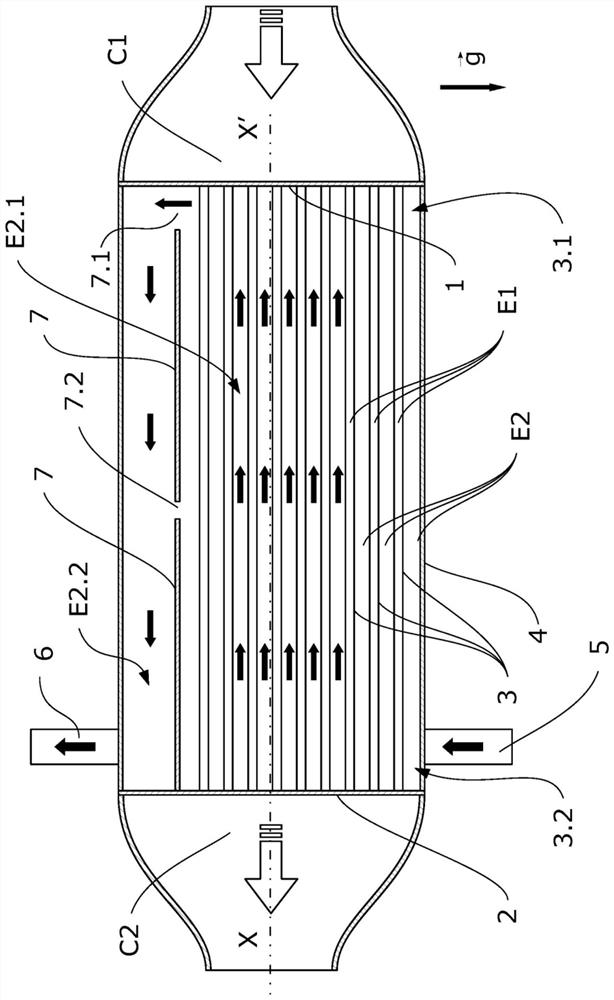
[0065] According to a first inventive aspect, the invention relates to a device for exchanging heat in an EGR system, wherein the temperature of a portion of the hot gas coming from the combustion chamber, identified as the first fluid, must be reduced in order to be able to It is reintroduced into the air intake, reducing the amount of nitrogen oxides in the exhaust.

[0066] The heat exchange device described has said purpose, wherein heat from a first fluid is dissipated to a second fluid, namely a liquid coolant.

[0067] The described embodiments solve the identified problems caused by the boiling of the liquid coolant in contact with the hotter surfaces where the heat exchange takes place, particularly in baffles that directly receive the hot gas.

[0068] figure 1 is a schematic view of a first embodiment of the invention, depicting a longitudinal section of a heat exchanger according to this first example.

[0069] The heat exchanger comprises a hot gas inlet, wherei...


PUM


Abstract

The present invention relates to a heat exchanger device for EGR ("Exhaust Gas Recirculation") systems, with a constructive solution which minimizes thermal fatigue when boiling occurs. The invention is characterized by a specific configuration of the inner space of the shell divided into a first exchange sub-space and a second degassing space communicated with one another, and wherein the inlet and outlet ports are located at the end where the cold baffle is located.

Description

technical field [0001] The present invention relates to a heat exchanger arrangement for an exhaust gas recirculation (EGR) system with a constructive solution for minimizing thermal fatigue when boiling occurs. [0002] The present invention is characterized in that the inner space of the housing is divided into a specific configuration of a first exchange subspace and a second degassing space communicating with each other, and wherein the inlet port and the outlet port are located at the end where the cold baffle is located . Background technique [0003] One of the most research-intensive technical fields is that of heat exchangers intended for use in EGR systems in internal combustion engines, where the space requirements in the engine compartment require devices to be of the smallest possible size in order to retain a high rate of heat transfer. [0004] Likewise, the high performance demands of internal combustion engines require them to operate at high temperatures,...

Claims


Application Information

Patent Timeline
Patent Type & Authority Applications(China)
IPC IPC(8): F02M26/32
CPCF02M26/32F28D7/16F28D7/1607F28F9/005F28F9/22F28F2009/224F28F2265/18F02M26/29
Inventor 胡利奥·阿夫拉姆·卡雷拉加西亚克拉拉·迪亚兹博韦达乔斯·曼努埃尔·佩雷斯罗德里格斯贡萨洛·西莫·卡达尔达费利克斯·洛佩斯费雷罗玛丽亚·伊莎贝尔·门德斯卡尔沃胡安·路易斯·费尔南德斯比利亚努埃瓦鲁道夫·普列托
Owner BORGWARNER EMISSIONS SYST SPAIN S L U
Why Eureka
Try Eureka