New energy street lamp with quick mounting structure

A technology of installation structure and new energy, which is applied to parts with built-in power supply, lighting devices, and cleaning methods using tools, etc., can solve the problems of affecting the appearance of the city, inconvenient transportation and installation, and long length.

Active Publication Date: 2021-06-01
广东顺腾照明科技有限公司
View PDF7 Cites 2 Cited by
  • Summary
  • Abstract
  • Description
  • Claims
  • Application Information

AI Technical Summary

Problems solved by technology

[0004] The purpose of the present invention is: in order to solve the problem that the existing new energy street lamps do not have a mechanism that can store the pole body and adjust the height of the pole body. Due to its integrated design, it is long in length and inconvenient for transportation and installation. Adjusting the actual conditions of the installation site is not conducive to the street lamps to illuminate the required lighting site well. The existing new energy street lamps do not have a quick installation structure, the installation is more complicated, and requires a large number of personnel and machinery for installation, which consumes a lot of money. A lot of manpower and material resources are required. The existing new energy street lamps do not have a mechanism for cleaning the rod body. After the street lamp is used for a long time, the surface of the rod body is full of dust, which seriously affects the appearance of the city. The existing new energy street lamps are not equipped with street lamps. The mechanism for adjusting the angle is not conducive to the problem of good lighting for the installation site, and the proposed new energy street lamp with a fast installation structure

Method used


Image

  • New energy street lamp with quick mounting structure
  • New energy street lamp with quick mounting structure
  • New energy street lamp with quick mounting structure

Examples


Embodiment Construction

[0037] The following will clearly and completely describe the technical solutions in the embodiments of the present invention with reference to the accompanying drawings in the embodiments of the present invention. Obviously, the described embodiments are only some, not all, embodiments of the present invention. Based on the embodiments of the present invention, all other embodiments obtained by persons of ordinary skill in the art without creative efforts fall within the protection scope of the present invention.

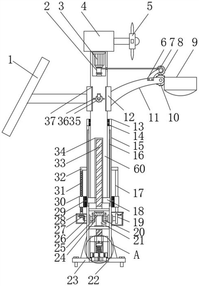
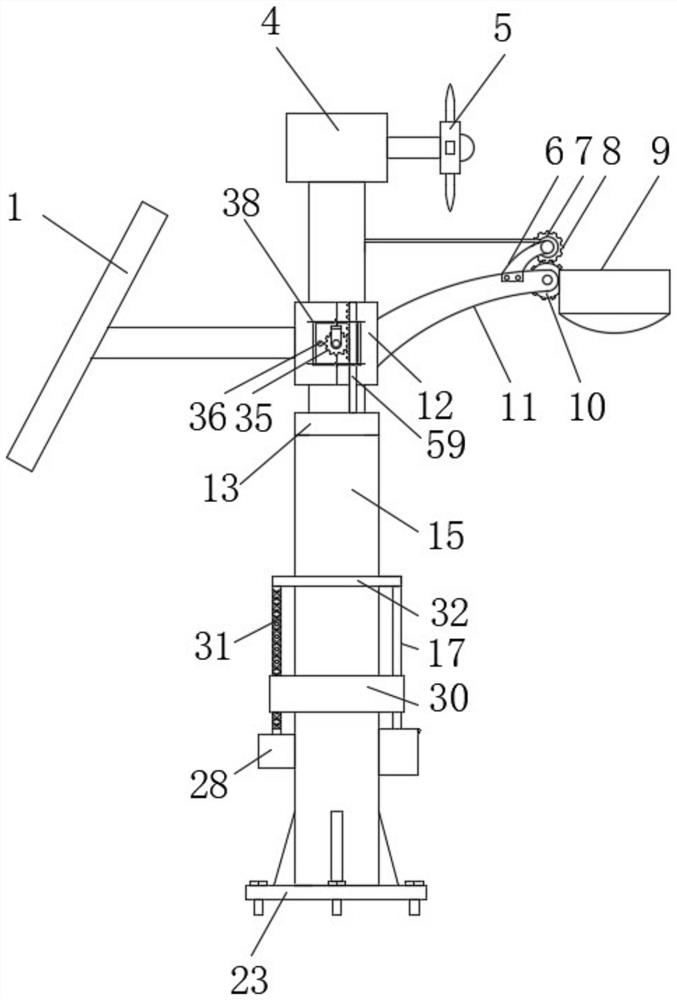
[0038] see Figure 1-6 , the present invention provides a technical solution: a new energy street lamp with a quick installation structure, including a mounting rod 15, a mounting base 43 and an adjusting rod 60, the lower surface of the adjusting rod 60 is fixedly installed with a base 18, and the mounting rod One side inner wall of 15 is provided with a chute 16, and the base 18 is slidably installed in the inside of the chute 16, and the inside of the adjusting ...


PUM


Abstract

The invention discloses a new energy street lamp with a quick mounting structure, and belongs to the technical field of new energy, the new energy street lamp comprises a mounting rod, a mounting seat and an adjusting rod, a base is fixedly mounted on the lower surface of the adjusting rod, a sliding groove is formed in the inner wall of one side of the mounting rod, and the base is slidably mounted in the sliding groove. According to the street lamp, adjustment is conducted according to the actual use height of the street lamp through an arranged first threaded column, the adjusting rod is driven to move upwards under the limitation of the base installed at the bottom when the first threaded column rotates through a first threaded groove in the adjusting rod, the base slides in the sliding groove in the mounting rod, and the street lamp is adjusted to the proper height; the rod body can be stored, the height of the rod body can be adjusted, and the problems that due to the fact that an existing street lamp is integrally designed, the length is large, transportation and installation are not convenient, adjustment cannot be conducted according to the actual situation of an installation site, and the street lamp cannot well illuminate the site needing illumination are solved.

Description

technical field [0001] The invention belongs to the technical field of new energy, and in particular relates to a new energy street lamp with a fast installation structure. Background technique [0002] New energy, also known as unconventional energy, refers to various forms of energy other than traditional energy, and refers to energy that has just begun to be developed and utilized or is being actively researched and to be promoted, such as solar energy, geothermal energy, wind energy, ocean energy, biomass energy and Nuclear fusion energy, etc., street lamps, as basic facilities in municipal construction, are installed in large numbers in every street in the city. With the enhancement of people's awareness of environmental protection and energy saving, new energy street lamps are gradually developing and popularizing. [0003] The existing new energy street lamps are not equipped with a mechanism that can store the pole body and adjust the height of the pole body. Due to ...

Claims


Application Information

Patent Timeline
Patent Type & Authority Applications(China)
IPC IPC(8): F21S9/03F21S9/02F21S9/04F21V21/14F21V21/10B08B1/00F21V21/30F21W131/103
CPCF21S9/035F21S9/026F21S9/043F21V21/14F21V21/10B08B1/008B08B1/001F21V21/30F21W2131/103Y02B20/72
Inventor 郑海君张岩颜
Owner 广东顺腾照明科技有限公司
Why Eureka
Try Eureka