A method for active control of tooth profile deviation of gear involute model

A technology of involute and tooth profile, applied in the field of precision machining and testing, can solve the problems of not introducing the accuracy and processing method of the gear involute sample, not satisfying, not involving tooth profile shape deviation, etc., and achieving a good market application prospect The effect of promoting value, ensuring consistency, and improving accuracy

Active Publication Date: 2021-12-03
DALIAN UNIV OF TECH
View PDF14 Cites 0 Cited by
  • Summary
  • Abstract
  • Description
  • Claims
  • Application Information

AI Technical Summary

Problems solved by technology

The above patents invented different structures of gear involute templates, but none of them introduced the precision and processing methods of gear involute templates. At present, none of the gear involute templates of our products meet the national standard GB / T 6467-2010 Requirements for Class 1 Precision Gear Involute Models
[0004] Invention patent [ZL201510091994] introduces a high-precision radially adjustable gear involute template and its adjustment method. By precisely adjusting the radial position of the gear involute template relative to the measuring mandrel, two involute templates can be simultaneously Or the tooth profile inclination deviation f of the 3 tooth surfaces Hα tend to be consistent, so as to ensure the consistency of the base circle radius of each tooth surface of the gear involute model, but this adjustment method relies on the adjustment screw adjustment, it is difficult to accurately control the adjustment amount in the actual use process, and it does not involve the tooth profile shape deviation f fα control method

Method used


Image

  • A method for active control of tooth profile deviation of gear involute model
  • A method for active control of tooth profile deviation of gear involute model
  • A method for active control of tooth profile deviation of gear involute model

Examples


Embodiment Construction

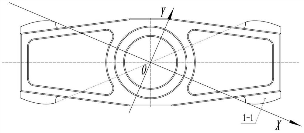
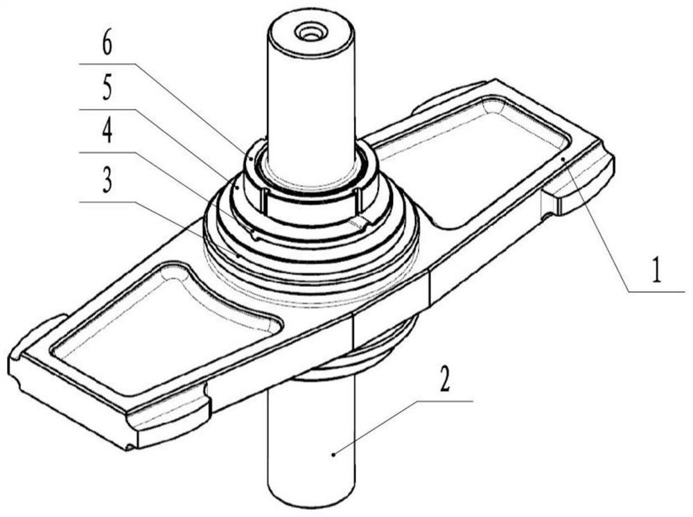
[0038] Take the initial base circle radius r b =100mm, value range 5~65mm, value length L α =60mm gear involute model 1 as an example, set forth the specific implementation of the invention:

[0039] The tooth surface to be regulated is a single tooth surface, that is, when the tooth surface to be regulated is A1-1:

[0040] The first step is to measure the initial tooth profile inclination deviation f of the tooth surface A1-1 to be controlled Hα =3.2μm, initial profile shape deviation f fα = 1.1μm, and separate the initial profile shape deviation f fα The profile crown deviation C in α = 0.3 μm;

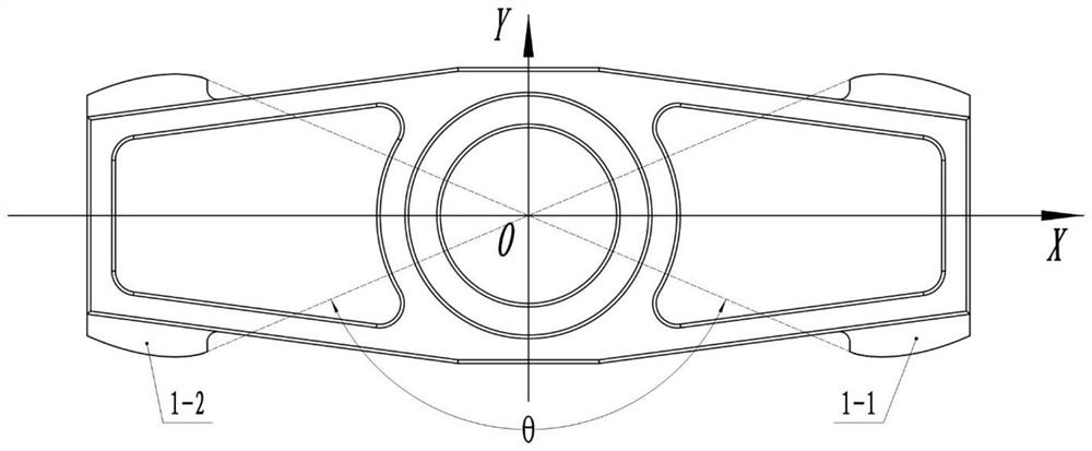
[0041] In the second step, take the center of the initial base circle as the origin, and take the line connecting the initial base circle center and the involute at the base circle as the X-axis to establish a right-handed coordinate system, and use the installation eccentricity e of the gear involute template 1 along the Y-axis direction y Control tooth profile shape deviation...


PUM


Abstract

The invention belongs to the technical field of precision machining and testing, and relates to a method for actively controlling the tooth profile deviation of a gear involute template. For a gear involute template whose tooth surface is a single tooth surface to be regulated, the installation of the gear involute template is controlled. Eccentricity makes the tooth profile convex deviation C of the gear involute model α tends to 0, thereby reducing the tooth profile shape deviation f fα ; For the gear involute model whose tooth surface to be regulated is two opposite tooth surfaces, by adjusting the installation eccentricity of the gear involute model, the tooth profile convexity deviation C α1 、C α2 Both tend to 0, thereby reducing the tooth profile shape deviation f fα1 , f fα2 , and can make the tooth profile inclination deviation f of the two opposite tooth surfaces Hα1 , f Hα2 Tends to be consistent; through this method, a first-class precision gear involute model that meets the requirements of the national standard GB / T 6467-2010 for gear involute models can be obtained, and the accuracy of existing commodity gear involute models can be improved without processing , has a good market application prospect and promotion value.

Description

technical field [0001] The invention belongs to the field of precision machining and testing, and relates to a method for actively controlling the tooth profile deviation of a gear involute model. Background technique [0002] The gear involute template is a standard measuring instrument for calibrating various involute measuring instruments. It is mainly used to transmit the gear involute parameter value, correct the instrument indication value and determine the instrument indication value error. The national standard GB / T6467-2010 for gear involute templates stipulates that the grades of gear involute templates are divided into grades 1 and 2. Tooth profile shape deviation f of the first-stage gear involute template fα Corresponds to the base circle radius r b ≤100mm, 100mm<r b ≤200mm, 200mm<r b ≤300mm and 300mm<r b ≤400mm are 1.0μm, 1.4μm, 1.7μm and 2.1μm respectively. Corresponding to the radius of the base circle in the above range, the tooth profile shap...

Claims


Application Information

Patent Timeline
Patent Type & Authority Patents(China)
IPC IPC(8): G01B5/20
CPCG01B5/202
Inventor 凌明凌四营邓云雷刘祥生杨洋王立鼎
Owner DALIAN UNIV OF TECH
Why Eureka
Try Eureka