
Mechanical arm tail end pose error measurement method and system

A technology of error measurement and robotic arm, applied in the direction of measuring device, image data processing, calculation model, etc., to achieve the effect of high-precision industrial robotic arm end pose error measurement and high industrial robotic arm end pose error measurement

Inactive Publication Date: 2021-06-01
FOSHAN POLYTECHNIC
View PDF6 Cites 0 Cited by
  • Summary
  • Abstract
  • Description
  • Claims
  • Application Information

AI Technical Summary

Problems solved by technology

[0004] The present invention provides a method and system for measuring the position and posture error of the end of the mechanical arm to solve one or more technical problems in the prior art, and at least provide a beneficial choice or create conditions

Method used


Image

  • Mechanical arm tail end pose error measurement method and system
  • Mechanical arm tail end pose error measurement method and system
  • Mechanical arm tail end pose error measurement method and system

Examples


Embodiment Construction

[0042] In order to make the objectives, technical solutions and advantages of the present invention clearer, the present invention will be further described in detail below with reference to the accompanying drawings and embodiments. It should be understood that the specific embodiments described herein are only used to explain the present invention, but not to limit the present invention.

[0043] It should be noted that although the functional modules are divided in the schematic diagram of the system and the logical sequence is shown in the flowchart, in some cases, the modules can be divided differently from the system, or executed in the order in the flowchart. steps shown or described. The terms "first", "second" and the like in the description and claims and the above drawings are used to distinguish similar objects and are not necessarily used to describe a specific order or sequence.

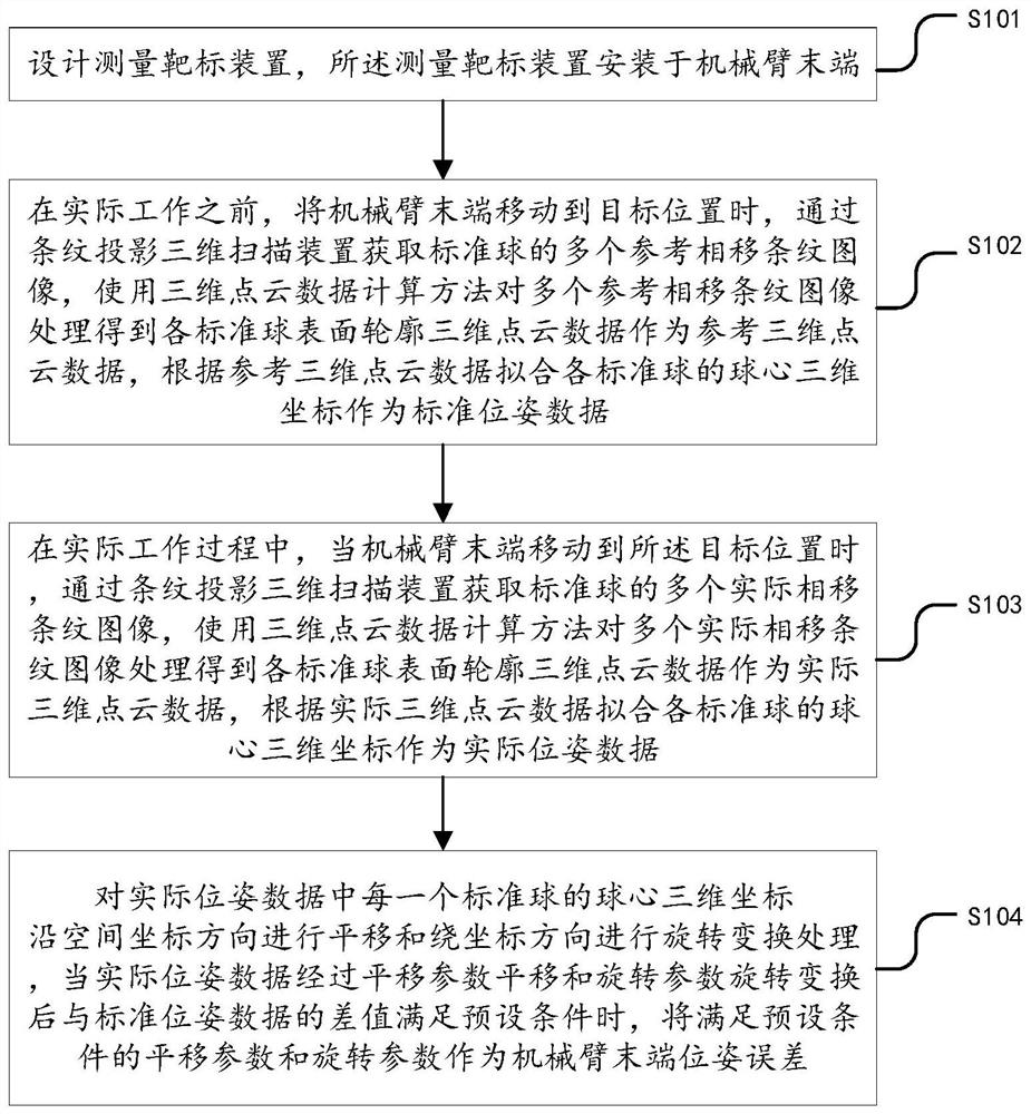
[0044] figure 1 It is a method for measuring the position and attitude error of a...


PUM


Abstract

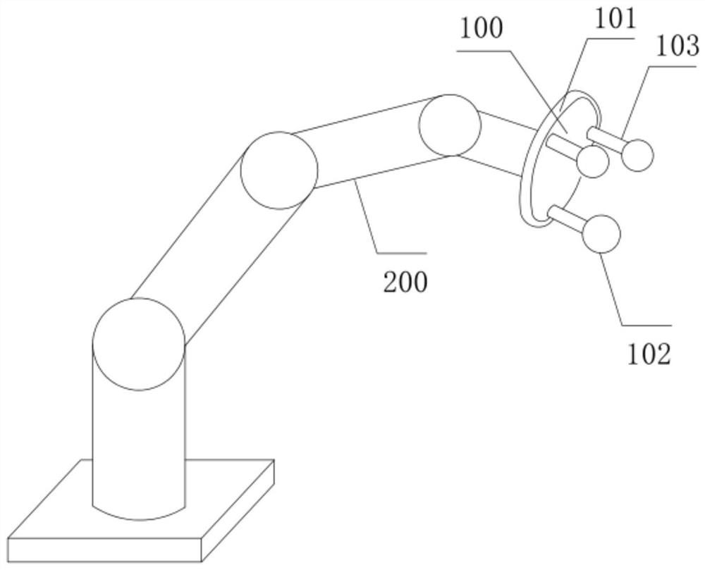
The invention discloses a mechanical arm tail end pose error measurement method and system. The system comprises a measurement target device, a mechanical arm, a fringe projection three-dimensional scanning device and a processor. The measurement target device comprises a base, a plurality of standard balls and a plurality of supporting rods, one end of each supporting rod is fixed to the base, the other end of each supporting rod is used for fixing one standard ball, the multiple supporting rods are annularly distributed, and the measurement target device is installed at the tail end of the mechanical arm. The standard pose of the tail end of the mechanical arm is obtained in advance without external influence, the standard pose is directly compared with the actual pose of the tail end of the mechanical arm in actual work, and pose errors are rapidly measured; besides, a large amount of three-dimensional point cloud data on the surface of the reference ball is obtained, the positions of all the ball centers are fitted through the three-dimensional point cloud data, a large amount of point cloud data is used in the calculation process, a small amount of data with large errors has small influences on the measurement result, and higher-precision industrial mechanical arm tail end pose error measurement can be achieved.

Description

technical field [0001] The invention relates to the field of industrial manipulators, in particular to a method and a system for measuring the position and attitude error of the end of a manipulator. Background technique [0002] The industrial manipulator has the characteristics of simple structure and convenient operation. It can replace manpower to realize automation and intelligent production, and can improve production efficiency, improve production environment and reduce product cost. It has been more and more used in enterprises. Although industrial manipulators have been widely used in dangerous work such as product handling or paint spraying, the overall mechanical structure of industrial manipulators is a tandem structure with weak structural rigidity, and it is difficult to achieve high positioning accuracy during the work process. The positioning error can even reach 2-3 mm, which greatly limits its further application in high-precision manufacturing occasions. ...

Claims


Application Information

Patent Timeline
IPC IPC(8): G01B11/00G06T7/00G06T7/11G06T7/136G06T7/62G06T7/73G06N3/00
CPCG01B11/005G06T7/0004G06T7/11G06T7/136G06T7/62G06T7/73G06T2207/10028G06T2207/30164G06N3/006
Inventor 张炜耿金华朱炯光邵鹏尹树彬
Owner FOSHAN POLYTECHNIC
Learn More