Integrated circuit pin three-dimensional detection system and detection technology

A technology of three-dimensional detection and integrated circuits, applied in measuring devices, material analysis through optical means, instruments, etc., can solve problems such as difficult clamping and removal, decreased product qualification rate, cumbersome clamping operations, etc., and achieves simple structure, The effect of taking out the chip easily

Inactive Publication Date: 2021-06-01
操佳兵
View PDF0 Cites 8 Cited by
  • Summary
  • Abstract
  • Description
  • Claims
  • Application Information

AI Technical Summary

Problems solved by technology

If only the electrical performance of the packaged chip is tested and the appearance inspection is ignored, chips with qualified electrical performance but defective appearance may be output, which will inevitably lead to a decline in the product qualification rate and affect the product brand.
[0003] However, traditionally, the appeara

Method used


Image

  • Integrated circuit pin three-dimensional detection system and detection technology
  • Integrated circuit pin three-dimensional detection system and detection technology
  • Integrated circuit pin three-dimensional detection system and detection technology

Examples


Embodiment 1

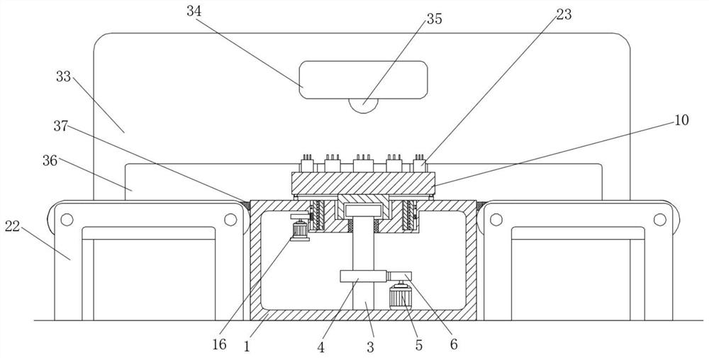
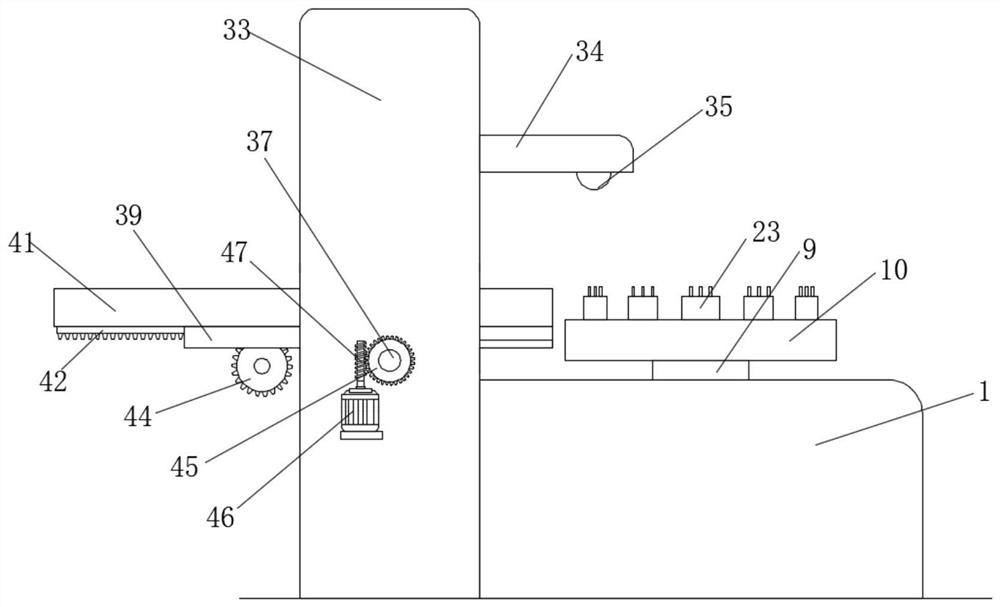
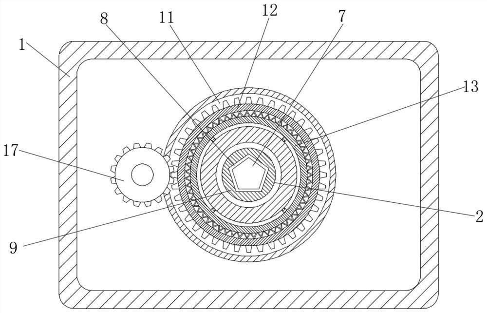
[0052] refer to Figure 1-15 , a three-dimensional detection system for integrated circuit pins, including a workbench 1, a circular groove 2 is arranged on the top of the workbench 1, a cylinder 9 is slidingly connected to the top of the circular groove 2, and a pentagonal groove 8 is arranged in the cylinder 9 , the top of the cylinder 9 is fixedly connected with a turntable 10, the workbench 1 is provided with a rotating assembly for making the turntable 10 rotate intermittently at 45 degrees, and the workbench 1 is provided with a pusher for pushing the turntable 10 and the cylinder 9 upwards. Assemblies, both sides of the workbench 1 are equipped with conveyor belts 22, and the top of the turntable 10 is arranged with a plurality of clamping boxes 23 equidistantly arranged in a ring with the cylinder 9 as the center of the circle. Chips 27 are arranged in the clamping boxes 23. A clamping assembly for clamping the chip 27 is provided in the box 23, a support 33 is fixedly...

Embodiment 2

[0068] Embodiment two: if Figure 16 As shown in -18, a three-dimensional detection system for integrated circuit pins, the difference between this embodiment and Embodiment 1 is that: the inner wall of the bottom of the groove 18 is fixedly connected with a support block 19, and the support block 19 is slidably connected with a slide bar 20, The end of the slide bar 20 away from the circular groove 2 touches the second ring 13, the outer wall of the slide bar 20 is provided with a tension spring 21, and the end of the tension spring 21 away from the circular groove 2 is fixedly connected with the support block 19, and the tension spring 21 One end away from the support block 19 is fixedly connected to the outer wall of the slide bar 20. When the slot 15 is flush with the slide bar 20, the slide bar 20 slides to the left under the tension of the tension spring 21 and extends into the slot 15. Two circular rings 13 brake.

[0069] However, as those skilled in the art know, the...


PUM


Abstract

The invention belongs to the technical field of integrated circuit detection, and particularly relates to an integrated circuit pin three-dimensional detection system and a detection technology. The integrated circuit pin three-dimensional detection system comprises a workbench, the top of the workbench is provided with a circular groove, the top of the circular groove is slidably connected with a cylinder, the cylinder is internally provided with a pentagonal groove, a rotating disc is fixedly connected to the top of the cylinder, and a rotating assembly used for enabling the rotating disc to intermittently rotate by 45 degrees is arranged in the workbench. The system is simple in structure, the chip can be clamped by pressing the chip into the clamping box, clamping of the chip can be relieved by rotating a rotating rod, the chip can be conveniently taken out, when the arc-shaped gear rotates by one circle, the first gear can be driven to rotate by 45 degrees, a chip can be accurately conveyed to the position under the CCD camera, the chip can be accurately detected through the CCD camera, manual operation is not needed in the detection process, the detection efficiency is improved, and the labor intensity of workers is reduced.

Description

technical field [0001] The invention relates to the technical field of integrated circuit detection, in particular to a three-dimensional detection system and detection technology for integrated circuit pins. Background technique [0002] Integrated circuit chips (IC) need to be inspected to ensure their quality after the packaging process is completed; and the three-dimensional appearance inspection of the packaged chip pins is an important part of the packaged chip inspection process. If only the electrical performance of the packaged chip is tested and the appearance inspection is neglected, chips with qualified electrical performance but defective appearance may be output, which will inevitably lead to a decline in the product qualification rate and affect the product brand. [0003] However, traditionally, the appearance inspection of packaged chips is usually carried out by manual visual inspection, but this method obviously has the defects of low efficiency and high l...

Claims


Application Information

Patent Timeline
IPC IPC(8): G01N21/84G01N21/01G01N21/13
CPCG01N21/01G01N21/13G01N21/84
Inventor 不公告发明人
Owner 操佳兵
Why Eureka
Try Eureka