


Quick Research
Generate reliable direction feasibility study reports for your R&D in just a few steps.

Technical Q&A
Discover and master advanced knowledge NOW. Basics, ideas, possibilities, all at once.

Find Solutions
As an expert in R&D theories, this can generate solutions to your technical problems instantly.

Evaluate Feasibility
Analyze your overall solution with one click, know your potential R&D risks in advance.

Monitor Landscape
Get weekly tech updates, stay abreast of the latest tech innovations and key insights.
Coil component
A technology of coil components and coils, applied in transformer/inductor parts, electrical components, transformer/inductor coils/windings/connections, etc., can solve problems such as reduced reliability and achieve high reliability
- Summary
- Abstract
- Description
- Claims
- Application Information
AI Technical Summary
Problems solved by technology
Method used
Image

Examples
no. 1 approach
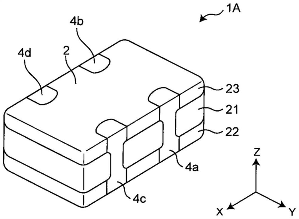
[0031]figure 1 It is a perspective view showing the coil member 1a according to the first embodiment of the present invention.
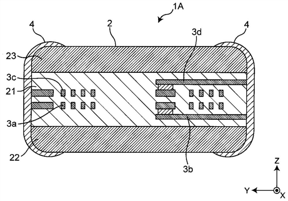
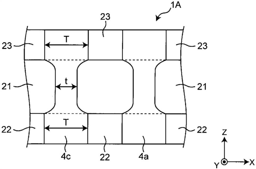
[0032]figure 2 It is a yz cross-sectional view of the coil member 1a.image 3 It is a partial end view of the coil member 1a.
[0033]Figure 4 It is an exploded perspective of the coil member 1a (but except for the external electrode).
[0034]Such asFigure 1 ~ 4 As shown, the coil member 1a is a so-called common mode choke coil, including a blank 2, a coil disposed inside the blank 2 (includingfigure 2 The first coil 3a and the second coil 3c are disposed on the outer electrode of the surface of the blank 2 (including the outer electrodes 4a, 4b, 4c, and 4d). The blank 2 includes a first glass layer 21, and a first ferrite layer 22 formed on the first main surface of the first glass layer 21 and a second ferrite formed on the second main surface of the first glass layer 21. The layer 23 (in addition, the first ferrite layer and the second ferrite layer are also kno...
no. 2 approach
[0083]Figure 6 It is a Yz cross-sectional view showing the coil member according to the second embodiment of the present disclosure.Figure 7 It is a partial side view of the coil component. The second embodiment differs from the first embodiment in that the blank 2 also includes a second glass layer 24 and a third glass layer 25. Only the different structures will be described below. Further, in the second embodiment, the same reference numerals as those in the first embodiment are the same as those of the first embodiment, and thus the description thereof will be omitted.
[0084]Such asFigure 6 as well asFigure 7 As shown, in the coil member 1b according to the second embodiment, the blank 2 may also include a second glass layer 24 laminated under the first ferrite layer 22 and laminated in the second ferrite layer 23. The third glass layer 25. In this case, the outer electrodes are present through the surface of the second glass layer 24, the first ferrite layer 22, the first glass ...
PUM
| Property | Measurement | Unit |
|---|---|---|
| Thickness | aaaaa | aaaaa |
| Thickness | aaaaa | aaaaa |
| Thickness | aaaaa | aaaaa |
Abstract
Description
Claims
Application Information
 - R&D Engineer
- R&D Manager
- IP Professional
- Industry Leading Data Capabilities
- Powerful AI technology
- Patent DNA Extraction
Browse by: Latest US Patents, China's latest patents, Technical Efficacy Thesaurus, Application Domain, Technology Topic, Popular Technical Reports.
© 2024 PatSnap. All rights reserved.Legal|Privacy policy|Modern Slavery Act Transparency Statement|Sitemap|About US| Contact US: help@patsnap.com