
Pipe gallery type jumper supporting structure and power transmission system and method

A support structure and pipe gallery technology, which is applied in the installation of electrical components, cables, overhead installation, etc., can solve the problems of cage jumper string discharge and irregular jumper wires, so as to improve electrical performance, ensure electrical characteristics, and avoid The effect of discharge

Active Publication Date: 2021-06-01
EAST INNER MONGOLIA ELECTRIC POWER COMPANY +4
View PDF14 Cites 0 Cited by
  • Summary
  • Abstract
  • Description
  • Claims
  • Application Information

AI Technical Summary

Problems solved by technology

[0004] At present, due to problems such as construction of the cage-type jumper string, the jumper wires of some jumper strings in the built project are irregular (that is, not in a straight state, because they are not stretched to a straight-line state), so that the cage-type jumper string There are often phenomena such as discharge at the string

Method used


Image

  • Pipe gallery type jumper supporting structure and power transmission system and method
  • Pipe gallery type jumper supporting structure and power transmission system and method
  • Pipe gallery type jumper supporting structure and power transmission system and method

Examples


Embodiment 1

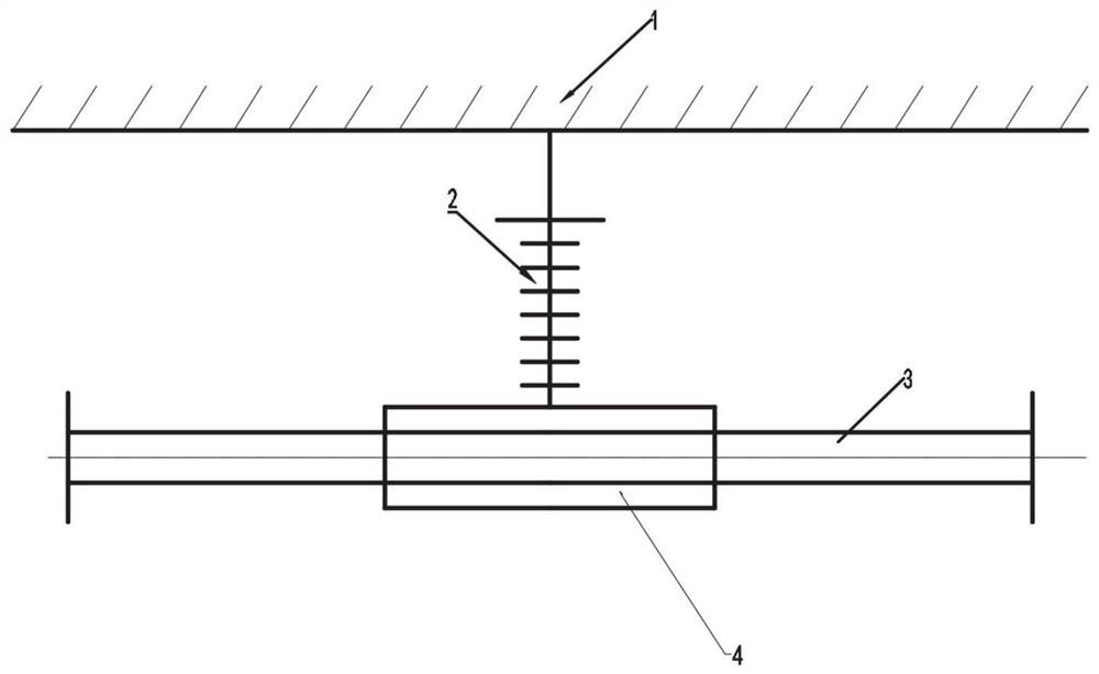
[0024] as attached figure 1 As shown, the present invention provides a pipe gallery support structure for a jumper, including: a sleeve, and several wire brackets connected to the sleeve; the wire bracket is used to fix several wires of the jumper to the sleeve tube inside. The direction in which the wire holder fixes the wire is parallel to the axial direction of the bushing.

[0025] Further, the casing includes several aluminum tubes, the casing is a pipe gallery structure, and the pipe gallery structure is a space formed by setting longitudinal connecting members, such as longitudinal beams or trusses, between adjacent aluminum pipes. The structure is a pipe gallery structure.

[0026] Further, the cross-section of the casing is square, oval or polygonal, preferably circular; the casing is split and formed by splicing several arc-shaped tubes.

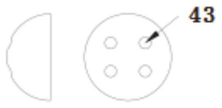
[0027] Further, the sleeve is formed by splicing two semicircular tubes.

[0028] Further, the wire bracket includes a suppor...

Embodiment 2

[0039] A method of using the jumper pipe gallery type support structure described in the above embodiment, the steps include:

[0040] Depending on the voltage level, the length of the jumper is different, that is, the length of the support mechanism of the pipe gallery jumper is also different, and the number of wire suspension brackets installed inside is also determined.

[0041] When installing, first fix the jumper on the wire clip of the wire bracket, and the wire clip will hold the jumper through the action of the built-in spring. The type of wire clip of this structure is convenient for construction. Sure.

[0042] Then put the sleeve of the pipe gallery jumper support mechanism, that is, the aluminum tube (split type, composed of two semicircular aluminum tubes) on the outside of the jumper, and fix it with the fixing bracket of the suspension bracket through fasteners , and finally cover the end cap and fasten it with fasteners; the fasteners can be bolts, pins, scr...


PUM


Abstract

The invention provides a pipe gallery type jumper supporting structure, which comprises a sleeve and a plurality of wire supports connected with the sleeve, wherein the wire support is used for fixing a plurality of wires of the jumper in the sleeve; during installation, the wires are fixed on a wire clamp of the wire support, and the wire clamp holds the wires under the action of a built-in spring; and the sleeve of the pipe gallery type jumper supporting mechanism is arranged on the outer side of the wire in a sleeving mode and fixed to a fixing support of a hanging support through a fastener, and finally a sealing end cover is covered and fastened through the fastener. The electrical characteristics of the jumper can be stably and effectively ensured, the phenomena of discharge and the like caused by irregularity of the jumper are reduced, and the electrical performance of the jumper is improved.

Description

technical field [0001] The invention relates to a pipe gallery type jumper support structure for jumper strings of overhead power transmission lines, a power transmission system and a method. Background technique [0002] The conductive device connecting the tension clamps of the conductors on both sides of the tension tower is called an overhead transmission line jumper. The jumper string is used to ensure sufficient electrical distance between the charged wire and the conductive part of the tower. [0003] At present, my country's UHV project construction has entered the stage of comprehensively accelerating construction, and the supporting power grids at all levels are developing rapidly. During the construction of power grids at all levels, the proposal of new fittings and new construction methods is of vital importance to the development of engineering construction and technology. effect. At present, for low-voltage levels, such as 110kV transmission lines, many jumper...

Claims


Application Information

Patent Timeline
Patent Type & Authority Applications(China)
IPC IPC(8): H02G7/00H02G3/04
CPCH02G7/00H02G3/0481
Inventor 罗汉武钱文晓祝永坤张军王景朝刘会斌王延伟李昉郭金刚刘胜春周立宪李博张小明孟杰游溢
Owner EAST INNER MONGOLIA ELECTRIC POWER COMPANY
Learn More