Lens assembly for super-resolution microscopy

A lens component and super-resolution technology, applied in microscopes, analytical materials, optical components, etc., can solve problems such as microscope resolution limitations

Pending Publication Date: 2021-06-01
UK RES & INNOVATION LTD
View PDF0 Cites 0 Cited by
  • Summary
  • Abstract
  • Description
  • Claims
  • Application Information

AI Technical Summary

Problems solved by technology

[0002] The resolution of conventional microscopes is limited due to the diffraction of light, and the achievable spatial resolution is roughly determined by the Abbe diffraction limit

Method used


Image

  • Lens assembly for super-resolution microscopy
  • Lens assembly for super-resolution microscopy
  • Lens assembly for super-resolution microscopy

Examples


Embodiment Construction

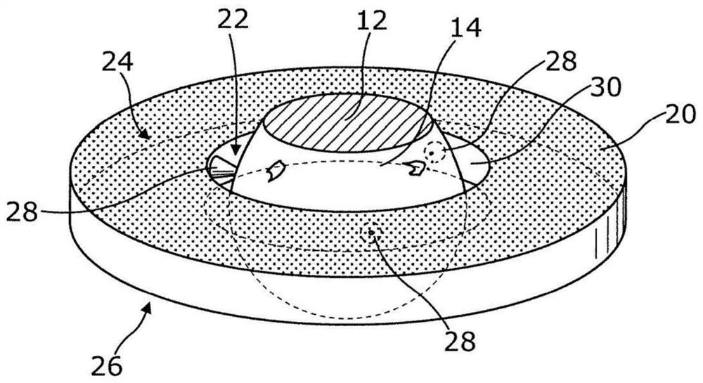
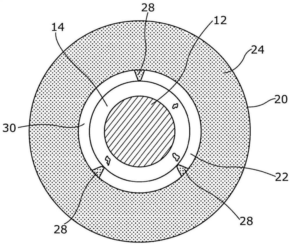
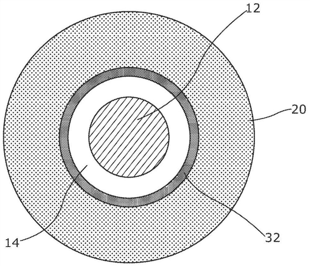
[0037] now refer to figure 1 , shows a perspective view of a lens assembly 10, which is used for microscopy of a sample in a cryogenic environment, such as super-resolution optical microscopy. exist figure 2 The corresponding floor plan is shown in , and image 3 The corresponding plan views of the adhesive material described below are shown also in place. For clarity, figure 1 and figure 2 Adhesive materials commonly used in these arrangements are omitted.

[0038] A sample (not shown in these figures) for imaging or other analysis using the microscope may be located adjacent to or in contact with plane 12 of solid immersion lens 14 . Specifically, and as figure 1 As shown, it can be provided as a non-planar solid state immersive lens (ASIL), which takes the form of a truncated spherical lens discussed in more detail below. The lens assembly also includes a planar base 20 having opposed and generally parallel major faces 24, 26 that are positioned between figure 1 a...


PUM

PropertyMeasurementUnit
diameteraaaaaaaaaa
diameteraaaaaaaaaa
thicknessaaaaaaaaaa

Abstract

A lens assembly, for use in microscopy imaging of a sample in a cryogenic environment, is described. A solid immersion lens which has a planar surface for accepting a sample for imaging is mounted within an aperture provided through the plane of a planar mount. The microscopy imaging may include using super-resolution optical imaging techniques such as single molecule localisation techniques.

Description

technical field [0001] The present invention relates to lens assemblies for microscopic imaging of samples located in cryogenic environments, and methods of constructing and using such lens assemblies. For example, microscopic imaging can include super-resolution optical imaging using techniques such as single-molecule localization techniques. Background technique [0002] The resolution of conventional microscopes is limited due to the diffraction of light, and the achievable spatial resolution is roughly determined by the Abbe diffraction limit. Therefore, the achievable spatial resolution depends on the optical parameters (e.g., the numerical aperture of the objective lens), and the numerical aperture can be increased in various ways (e.g., by using liquid immersion techniques), where fluids with high refractive index are used for optical coupling Objective lens and sample to be imaged. [0003] Various additional techniques have also been developed in the prior art to ...

Claims


Application Information

Patent Timeline
Patent Type & Authority Applications(China)
IPC IPC(8): G02B21/02G02B7/02
CPCG02B7/02G02B21/02G02B27/58G02B21/16G02B21/0088G01N21/6458
Inventor 山姆·阿斯特伯里马丁·托利克里斯托弗·斯宾德洛
Owner UK RES & INNOVATION LTD
Why Eureka
Try Eureka