Roller type tool apron

A technology of tool seat and roller type, which is applied in metal processing and other directions, can solve the problems of complicated debugging process, inability to adjust the mutual positions of the tool shafts in the axial direction, and difficult installation of the tool shafts.

Pending Publication Date: 2021-06-04
廊坊纽特科技有限公司
View PDF0 Cites 0 Cited by
  • Summary
  • Abstract
  • Description
  • Claims
  • Application Information

AI Technical Summary

Problems solved by technology

[0004] The purpose of the present invention is to provide a roller-type tool holder to solve the complex assembly and debugging process of the tool holder proposed in the above-mentioned background technology, and it is difficult to ensure the installation accuracy; The mouth slides downwards, which has low matching precision and affects the running accuracy of the knife shaft; the structure of the knife seat is a steel plate assembly structure, arranged in a straight line on the base of the die-cutting machine, and fixedly installed on the horizontal base platform, the knife seat cannot be moved and adjusted , making it difficult to install the cutter shafts, especially the lower ones, and the axial mutual positions of the cutter shafts between the two sets of tool holders cannot be adjusted, which reduces the accuracy of die-cut products

Method used


Image

  • Roller type tool apron
  • Roller type tool apron
  • Roller type tool apron

Examples


Embodiment Construction

[0028] The following will clearly and completely describe the technical solutions in the embodiments of the present invention with reference to the accompanying drawings in the embodiments of the present invention. Obviously, the described embodiments are only some, not all, embodiments of the present invention.

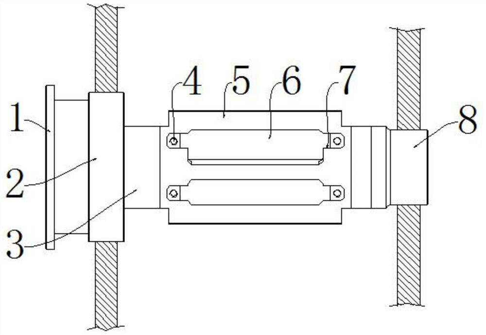
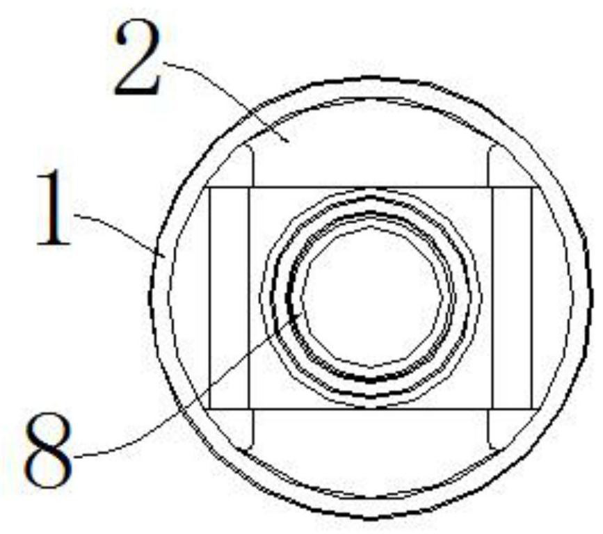
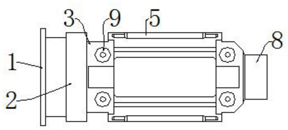
[0029] see Figure 1-8 , an embodiment provided by the present invention: a roller knife holder, including a roller knife holder main body 2 and a rib plate 5, a flange plate 1 is installed on one end of the roller knife holder main body 2, and the flange plate 1 is convenient for the motor Or the installation of the reducer, the roller tool holder main body 2 is provided with a guide rod installation hole 9, and the guide rod is installed in the guide rod installation hole 9, and the upper and lower sides of the roller tool holder main body 2 are provided with stepped grooves 7 and screw holes 4.

[0030] Further, a hollow mouth 6 is provided between the rib plate ...


PUM


Abstract

The invention discloses a roller type tool apron which comprises a roller type tool apron body and rib plates, a flange plate is installed at one end of the roller type tool apron body, a guide rod installation hole is formed in the roller type tool apron body, a guide rod is installed in the guide rod installation hole, and stepped grooves and screw holes are formed in the upper side and the lower side of the roller type tool apron body. According to the roller type tool apron, the exterior of the roller type tool apron is of a cylindrical structure, and the roller type tool apron is installed in an installation hole of a die-cutting machine base equipment plate and can do rotary motion and axial linear motion, so that a lower tool shaft can be conveniently rotated to the upper portion to be installed, the tool installation convenience is improved, and overall axial adjustment of a tool apron assembly is achieved. The adjustment and alignment convenience and accuracy of tools of the tool apron assemblies are improved. Eight installation holes are machined in the tool apron body and used for installing guide rods and guaranteeing accurate positioning of a tool shaft sliding block, so that the installation accuracy of a tool shaft is improved, and due to the fact that the tool apron is an integrally-machined part, the installation accuracy of a motor and a speed reducer can be improved.

Description

technical field [0001] The invention relates to the related field of die-cutting machines, in particular to a roller-type knife seat. Background technique [0002] At present, plastic, metal foil, graphene and other components are widely used in the manufacturing process of electronics, communications, office, medicine, non-telecom, packaging, daily necessities and other products, which require precise die-cutting. [0003] In the existing die-cutting machine, the structure of the knife seat is a steel plate assembly structure, which is arranged in a straight line on the base of the die-cutting machine and fixedly installed on the horizontal base platform. The knife seat cannot be moved and adjusted. The disadvantages are: the assembly and debugging of the knife seat The process is complicated, and it is difficult to ensure the installation accuracy; the cutter shaft is installed in the rectangular slider, and the slider slides down along the notch of the tool holder, which ...

Claims


Application Information

Patent Timeline
IPC IPC(8): B26F1/38B26D7/26
CPCB26D7/2614B26F1/384
Inventor 魏顺永桑俊宝杨海生
Owner 廊坊纽特科技有限公司
Why Eureka
Try Eureka