Eureka AIR delivers breakthrough ideas for toughest innovation challenges, trusted by R&D personnel around the world.

Filling and conveying equipment based on burn ointment production and processing

A technology for conveying equipment and burn ointment, which is applied to the safety device, packaging, bottling machine and other directions of the perfusion device, can solve the problems of inconvenient use, narrow use matching degree, and reduce the efficiency of the ointment factory, and achieves convenient use and use matching degree. high effect

Inactive Publication Date: 2021-06-04
周爱丽
View PDF0 Cites 1 Cited by
  • Summary
  • Abstract
  • Description
  • Claims
  • Application Information

AI Technical Summary

Problems solved by technology

[0006] The purpose of the present invention is to provide a filling and conveying equipment based on the production and processing of burn ointment, which has the advantages of being able to be separated separately, having a high matching degree in use, and being able to inspect canned bottles, and solves the problem of the device for injecting ointment on the equipment. It cannot be separated separately, it is inconvenient to use, and the injection device cannot be separated, so it is difficult to move and replace according to the actual use environment, which is limited and inconvenient, and can only be used with one transmission device, which is difficult to meet other transmission devices. Narrow, restricted, and inconvenient. The traditional conveying device has no inspection device. It is difficult to inspect whether the bottle cap is tightly closed when the canned bottle leaves the factory. Therefore, poor sealing often occurs, resulting in loss of ointment efficacy. , reduce the quality of the ointment, and reduce the efficiency of the ointment

Method used


Image

  • Filling and conveying equipment based on burn ointment production and processing
  • Filling and conveying equipment based on burn ointment production and processing
  • Filling and conveying equipment based on burn ointment production and processing

Examples


Embodiment Construction

[0034] The following will clearly and completely describe the technical solutions in the embodiments of the present invention with reference to the accompanying drawings in the embodiments of the present invention. Obviously, the described embodiments are only some, not all, embodiments of the present invention. Based on the embodiments of the present invention, all other embodiments obtained by persons of ordinary skill in the art without making creative efforts belong to the protection scope of the present invention.

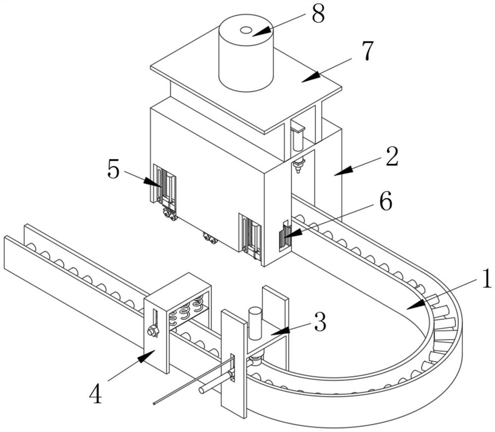
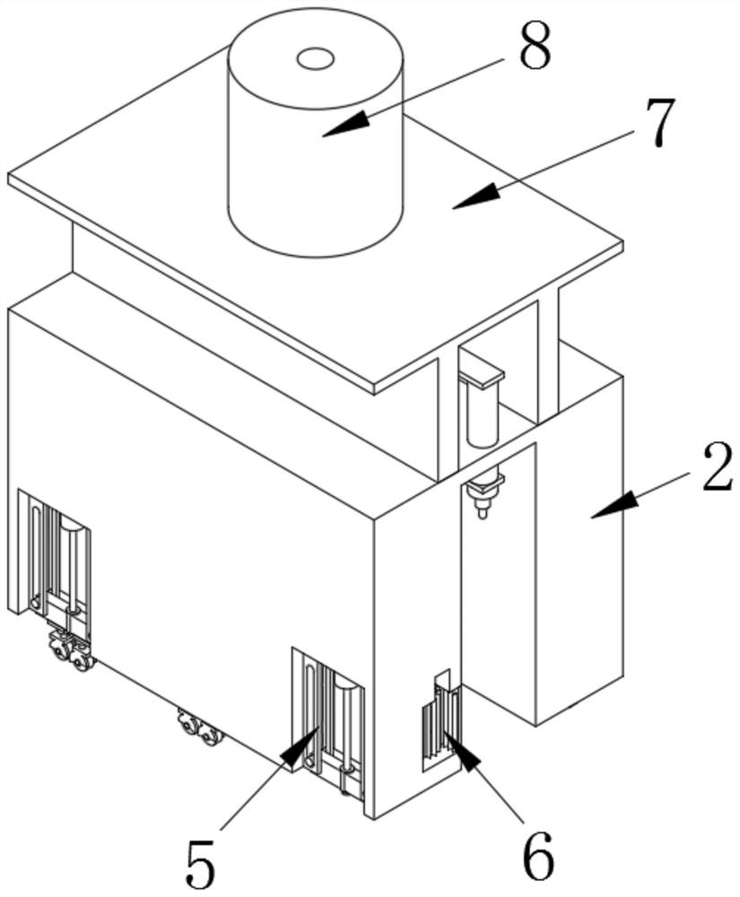
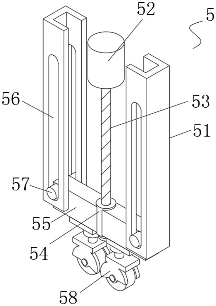
[0035] see Figure 1-9 , the present invention provides a technical solution, a kind of filling and conveying equipment based on the production and processing of burn ointment, including a mobile transmission device 1, one end of the surface of the mobile transmission device 1 is provided with a mounting frame 2, and the other end of the surface of the mobile transmission device 1 is provided with There are cover loading mechanism 3 and inspection device 4, two ...


PUM


Abstract

The invention discloses filling and conveying equipment based on burn ointment production and processing. The equipment comprises a movable conveying device, wherein a mounting frame is arranged at one end of the surface of the movable conveying device, a capping mechanism and an inspection device are arranged at the other end of the surface of the movable conveying device, and two adjusting mechanisms are arranged on each of two sides of the mounting frame; a boosting mechanism is arranged on one side in the mounting frame, and a fixing frame is fixedly mounted at the top of the mounting frame. In actual use, the moving wheels can be released and hidden, so that the mounting rack can be mutually converted between moving and positioning, a user can conveniently move at any time, the mounting rack can be conveniently matched and assembled with other conveying equipment, different use environments can be met, convenience and rapidness are achieved, the time and labor are saved, and the mounting rack is suitable for popularization and application. By arranging the inspection device, the firmness of a bottle cap can be monitored, the delivery quality of the canned burn cream can be guaranteed, and a user can use the canned burn cream conveniently.

Description

technical field [0001] The invention relates to the technical field of burn ointment, in particular to a filling and conveying equipment based on the production and processing of burn ointment. Background technique [0002] Burn ointment, this prescription is an external ointment for detoxifying, reducing swelling, promoting muscle regeneration and soothing sores. It is mainly used for burns, scalds, chemical burns and other skin burn diseases. Erosion, or secondary infection, sores that have not healed for a long time; hemorrhoids with swelling, pain, bleeding, or incarcerated necrosis, ulceration, bleeding, and unbearable pain, should use this agent. [0003] In the production and processing of burn plasters, canned delivery equipment is used to fill the ointment cans into bottles and then deliver them out. However, traditional canned delivery equipment has the following defects: [0004] 1. The device for injecting ointment on the equipment cannot be separated separately...

Claims


Application Information

Patent Timeline
Patent Type & Authority Applications(China)
IPC IPC(8): B67C3/00B67C3/24B67C7/00
CPCB67C3/007B67C3/24B67C7/0026
Inventor 周爱丽
Owner 周爱丽
Why Eureka
Eureka Blog
Learn More