Automatic quick-freezing forming equipment for soapy water

A molding equipment and soapy water technology, which is applied in the field of soapy water automatic quick-freezing molding equipment, can solve the problems of low cooling efficiency of soapy water and the inability to automatically unload materials, etc., and achieve the effects of improving production efficiency, beautiful appearance, and improving molding efficiency

Inactive Publication Date: 2021-06-04
郭小光
View PDF6 Cites 2 Cited by
  • Summary
  • Abstract
  • Description
  • Claims
  • Application Information

AI Technical Summary

Problems solved by technology

[0005] In order to overcome the shortcomings of the low cooling efficiency of soapy water and the inability to automatically unload the material, the technical problem of the present invention is to provide a soapy water automatic quick-freezing molding equipment with high cooling efficiency and automatic unloading of soapy water

Method used


Image

  • Automatic quick-freezing forming equipment for soapy water
  • Automatic quick-freezing forming equipment for soapy water
  • Automatic quick-freezing forming equipment for soapy water

Examples


Embodiment 1

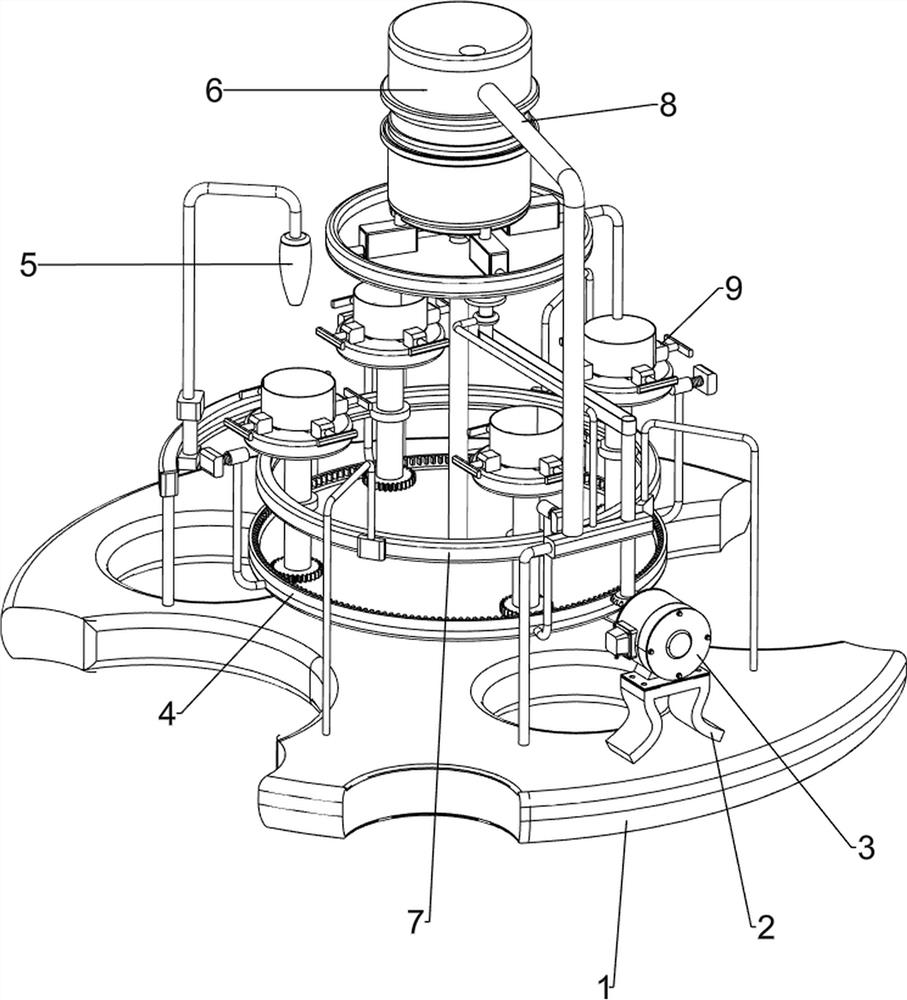
[0081] A kind of soapy water automatic quick-freezing molding equipment, such as figure 1 As shown, it includes a base plate 1, a first support column 2, a motor 3, a transmission mechanism 4, and a cooling mechanism 5. The upper front portion of the base plate 1 is provided with a first support column 2, and a motor 3 is installed on the top of the first support column 2. The base plate 1 is provided with a transmission mechanism 4 in the upper middle, and the transmission mechanism 4 is connected with the output shaft of the motor 3;

[0082] When people make soap, the cooling of soap takes a long time and the production efficiency is low. The present invention helps people improve the molding efficiency of soap. First, the model filled with soapy water is placed on the transmission mechanism 4, and the motor 3 and the cooling mechanism are started. After 5, the motor 3 drives the transmission mechanism 4 to run, and the transmission mechanism 4 drives the soapy water to rot...

Embodiment 2

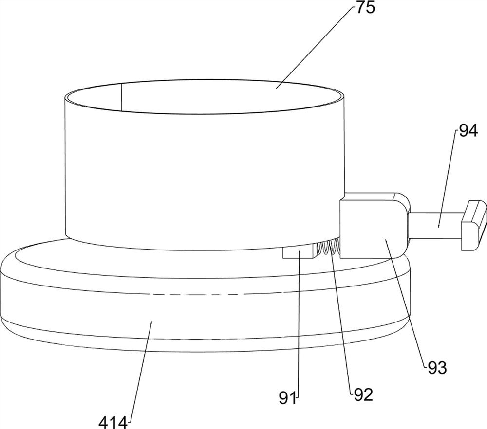
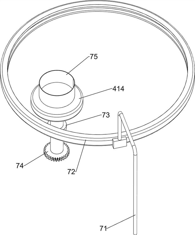
[0084] On the basis of Example 1, such as figure 2 and image 3 As shown, the transmission mechanism 4 includes a second support column 41, a support plate 42, a third support column 43, a first rotating shaft 44, a fourth supporting column 45, a second rotating shaft 46, a third rotating shaft 47, a bevel gear set 48, The first transmission assembly 49, the fourth rotating shaft 410, the first straight gear 411, the missing gear 412, the ring gear 413 and the turret 414, the upper front part of the bottom plate 1 is provided with the second support column 41, and the upper middle part of the bottom plate 1 is provided with a support plate 42. A third support column 43 is provided on the rear side of the upper part of the first support column 2. The upper part of the third support column 43 is rotatably provided with a first rotating shaft 44. The first rotating shaft 44 is connected to the output shaft of the motor 3. The top of the second supporting column 41 The fourth su...

Embodiment 3

[0089] On the basis of Example 2, such as figure 1 , Figure 4 , Figure 5 , Figure 6 and Figure 7 As shown, it also includes a feeding mechanism 6, the conveying mechanism 4 is provided with a feeding mechanism 6, the feeding mechanism 6 is connected with the bottom plate 1, and the feeding mechanism 6 includes a tray 61, a sixth support column 62, and a feeding box 63 , baffle plate 631, sliding sleeve 632, second connecting rod 64, material storage box 65 and discharge pipe 66, bottom plate 1 upper rear part is provided with tray 61, tray 61 is connected with the fourth rotating shaft 410 rotationally, the second support column The top of 41 is provided with a sixth support column 62, the top of the fourth rotating shaft 410 is rotatably provided with a loading box 63, and a sliding sleeve 632 is slidably connected between the loading box 63 and the sixth supporting column 62, and the top of the fourth rotating shaft 410 is provided with There are four second connecti...


PUM


Abstract

The invention relates to forming equipment, in particular to automatic quick-freezing forming equipment for soapy water. The automatic quick-freezing forming equipment forsoapy water is high in soapy water cooling efficiency and capable of achieving automatic discharging. The automatic quick-freezing forming equipment for soapy water comprises a bottom plate and a first supporting column, wherein the first supporting column is arranged on the bottom plate; a motor mounted on the first supporting column; a conveying mechanism arranged on the bottom plate, wherein the conveying mechanism is connected with an output shaft of the motor; and a cooling mechanism arranged on the bottom plate, wherein the cooling mechanism is connected with the conveying mechanism. The equipment achieves the effect of improving the soapy water forming efficiency; and through cooperation of the conveying mechanism and the cooling mechanism, soapy water can be solidified and formed through cold air, and the soapy water forming process is accelerated; and through cooperation of the feeding mechanism and the stirring mechanism, the automatic discharging effect is achieved.

Description

technical field [0001] The invention relates to a forming device, in particular to a soapy water automatic quick-freezing forming device. Background technique [0002] When people make soap, it takes a long time to cool the soap, and the production efficiency is low, and the surface of the soap is easy to form wrinkles during the molding process, which affects the appearance. [0003] The publication number is CN211445663U, which discloses a soap forming device, which includes a box body, a groove is arranged at the bottom of the box body, an extruding barrel is installed at the middle end of the groove inside, a stirring chamber is installed at the middle part of the upper end of the box body, and the bottom side of the stirring chamber is Discharge pipes are installed at the left and right ends, a rotating drum is installed at the middle end of the mixing chamber, a scraper is installed on the top of the mixing chamber outside the rotating drum, and a second air cylinder i...

Claims


Application Information

Patent Timeline
Patent Type & Authority Applications(China)
IPC IPC(8): C11D13/14C11D13/12
CPCC11D13/12C11D13/14
Inventor 郭小光
Owner 郭小光
Why Eureka
Try Eureka