Reaming device for geological exploration sampling

A technology for geological exploration and soil borrowing sleeves, which is applied in the directions of support devices, drilling equipment and methods, drilling equipment, etc., can solve the problems of affecting the effect of hole reaming, the difference in the falling speed of the drill bit affecting the reaming efficiency, and the falling of soil, etc. The effect of increasing the drilling rate

Pending Publication Date: 2021-06-04
QINGDAO PROSPECTING INST OF GEOLOGICAL ENG
View PDF8 Cites 0 Cited by
  • Summary
  • Abstract
  • Description
  • Claims
  • Application Information

AI Technical Summary

Problems solved by technology

[0003] In the existing reaming device for geological exploration, the hole wall will rebound to a certain extent after reaming during the reaming process, and the soil on the hole wall will easily fall into the hole, thereby affecting the reaming effect; at the same time, the existing The falling speed of the drill bit of the reaming device is poor, which affects the reaming efficiency

Method used


Image

  • Reaming device for geological exploration sampling
  • Reaming device for geological exploration sampling
  • Reaming device for geological exploration sampling

Examples


Embodiment 1

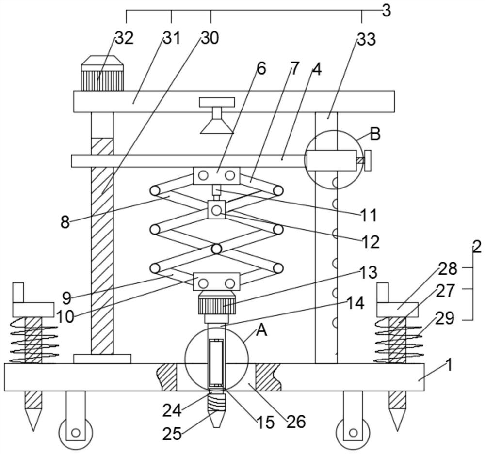
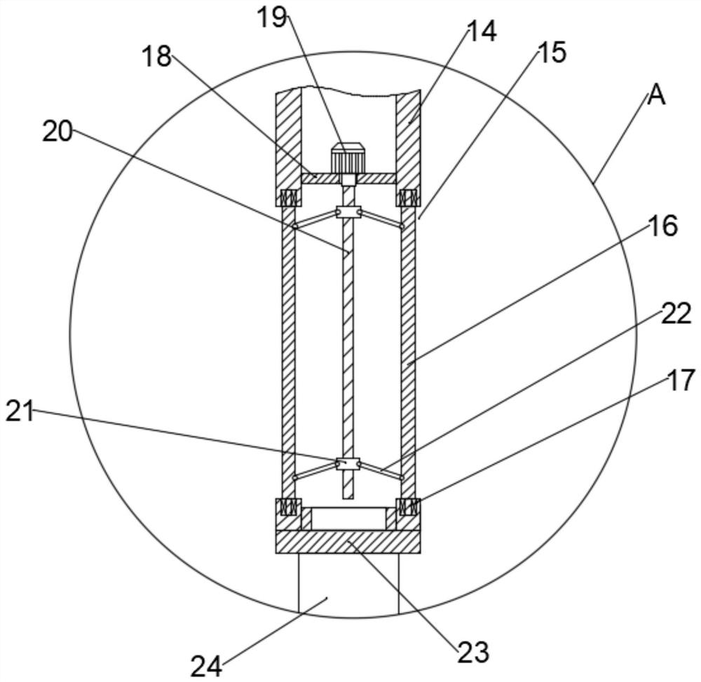
[0026] see Figure 1~6 , in an embodiment of the present invention, a geological prospecting sampling hole reaming device includes a base 1, a fixing mechanism 2 and a lifting mechanism 3, the fixing mechanism 2 and the lifting mechanism 3 are fixedly connected to the base 1, and the lifting mechanism 2 A lifting plate 4 is connected to the upper side of the lifting plate 4 and a positioning mechanism 5 is connected to one side of the lifting plate 4. The lower end surface of the lifting plate 4 is fixedly connected with a first U-shaped seat 6, and two relative rotations are connected in the first U-shaped seat 6. First connecting rod 7, two first connecting rods 7 lower ends are respectively connected with a articulated rod 8, and described articulated rod 8 has several, and every two articulated rods 8 are a group and the two articulated rods 8 of every group are equal to each other. Cross-symmetric hinged, the two lower ends of each set of hinged rods 8 are hinged with the...

Embodiment 2

[0036] The difference between this embodiment of the present invention and Embodiment 1 is that the fixing mechanism 2 includes a positioning rod 27, a rotating seat 28 and a spring 29, and four positioning rods 27 are arranged in a rectangular shape on the base 1 and the four positioning rods 27 All are threadedly connected with the base 1, the upper end of each positioning rod 27 is fixedly connected with a rotating seat 28 and each rotating seat 28 is connected with the base 1 by a spring 29, and the lower end of each positioning rod 27 is tapered;

[0037] The working principle of this embodiment: respectively rotate the rotating seat 28 at the upper end of the four positioning rods 27 to drive the fixedly connected positioning rods 27 and the base 1 to be threaded, so the positioning rods 27 move downward and insert the base 1 with the base 1 through the tapered end. The ground is fixed firmly, and the spring 29 connected between each rotating seat 28 and the base 1 can in...


PUM


Abstract

The invention discloses a reaming device for geological exploration sampling. A plurality of ports are annularly formed in the side wall of a soil sampling sleeve; a soil scraping plate is arranged in each port; rotating shafts are fixedly connected with the upper ends and the lower ends of the soil scraping plates; each rotating shaft is rotationally connected with the interior of the side wall of the soil sampling sleeve through a bearing; a supporting plate is fixedly connected with the interior of the soil sampling sleeve; a second rotating motor is fixedly connected with the supporting plate; an output shaft of the second rotating motor is fixedly connected with a threaded shaft; the threaded shaft is in threaded connection with two threaded sleeves; the side wall of each threaded sleeve is universally connected with a plurality of round rods at equal intervals; the other end of each round rod is correspondingly and universally connected with the inner end face of one soil scraping plate; the lower end of the soil sampling sleeve is in threaded connection with a lower end cover; the lower end face of the lower end cover is fixedly connected with a connecting shaft; and a drill bit is fixedly connected with the lower end of the connecting shaft. The reaming device for geological exploration sampling is good in hole expanding effect and high in hole expanding speed.

Description

technical field [0001] The invention relates to the field of geological exploration, in particular to a hole reaming device for sampling in geological exploration. Background technique [0002] Geological exploration is to investigate and detect the strata through various means and methods, determine the thickness of different strata, take core samples of rocks in different strata, and then determine the chemical and physical properties of rock minerals through testing and mechanical analysis. During the process, the drill holes need to be reamed to facilitate the experimenters to take samples. [0003] In the existing reaming device for geological exploration, the hole wall will rebound to a certain extent after reaming during the reaming process, and the soil on the hole wall will easily fall into the hole, thereby affecting the reaming effect; at the same time, the existing The falling speed of the drill bit of the reaming device is poor, which affects the reaming effici...

Claims


Application Information

Patent Timeline
IPC IPC(8): E21B7/28E21B7/02E21B15/00
CPCE21B7/28E21B7/02E21B15/00E21B15/003E21B15/006Y02A90/30
Inventor 徐红兵谭孟云周永生贾世祥曲万隆
Owner QINGDAO PROSPECTING INST OF GEOLOGICAL ENG
Why Eureka
Try Eureka