Flap valve magnetic closing performance test equipment and test method

A test equipment, flap valve technology, used in mechanical valve testing and other directions

Pending Publication Date: 2021-06-04
SICHUAN UNIV +1
View PDF1 Cites 2 Cited by
  • Summary
  • Abstract
  • Description
  • Claims
  • Application Information

AI Technical Summary

Problems solved by technology

However, this magnetic flap valve is only at the theoretical stage, a

Method used


Image

  • Flap valve magnetic closing performance test equipment and test method
  • Flap valve magnetic closing performance test equipment and test method
  • Flap valve magnetic closing performance test equipment and test method

Examples


Embodiment 1

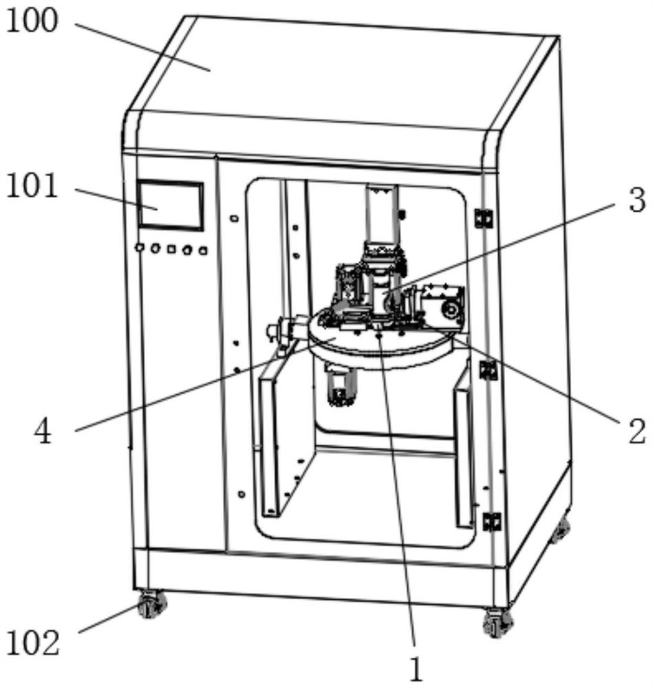
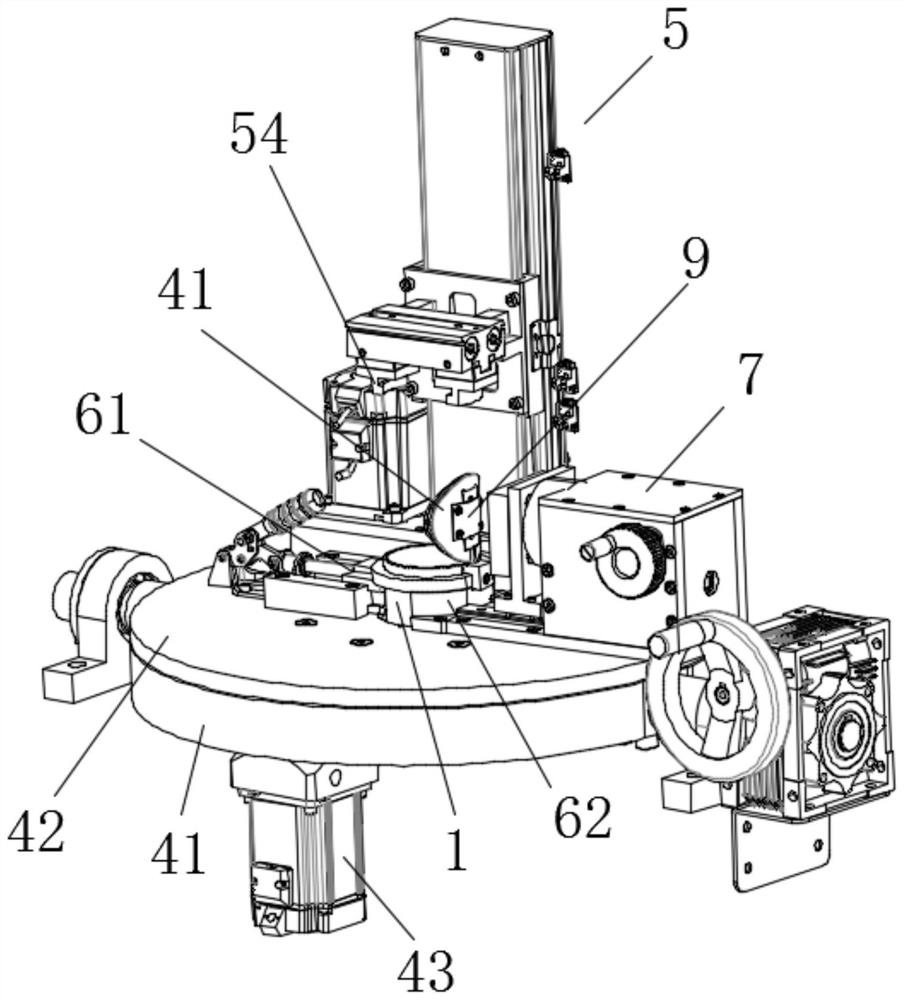
[0043] Such as figure 1 , figure 2 As shown, the magnetic closing performance testing equipment for the flap valve disclosed in this embodiment includes a box body 100 and a test bench. The test bench includes a platform 4, a valve seat fixing mechanism 6 for fixing the valve seat, and a core barrel driving mechanism 5 for driving the core barrel up and down.

[0044] The test bench is placed in the box body 100, and the box body 100 has an observation window. Putting the experimental platform in the box 100 has three functions: first, to realize the protection function. When the valve clack is closed, the air pressure is used to determine its pretightening force. second, to realize the modularization of the control mechanism, and to package each pneumatic and electric device in the box 100 to achieve a tidy and functional modular effect; third, the test bench not only has experimental functions, but also has certain functions. The valve seat closing action display functio...

Embodiment 2

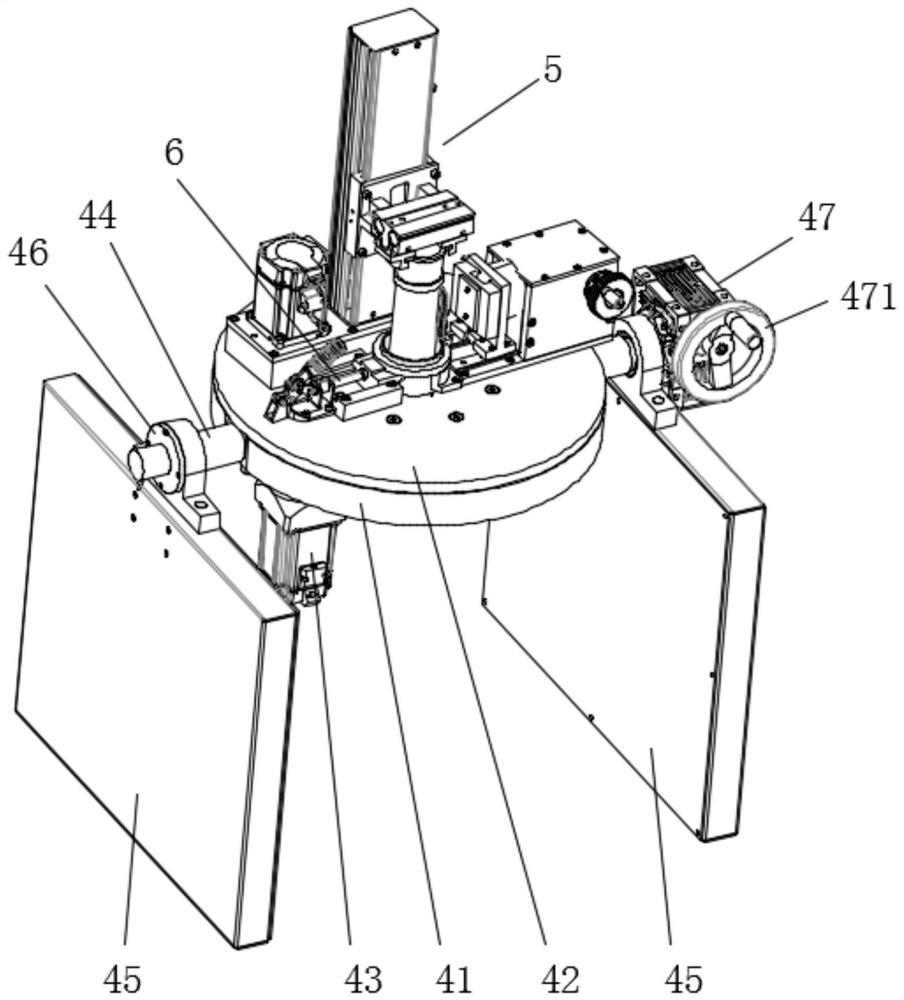
[0082] The difference between this embodiment and Embodiment 1 is that: in this embodiment, the first base 41 and the second base 42 are disc-shaped. The first base 41 is arranged parallel to the second base 42 . The two rotating shafts 44 are radially disposed on opposite sides of the first base 41 .

[0083] The supporting seat 45 is a plate shape arranged vertically, and the bearing seat 46 is mounted on the top of the supporting seat 45 .

[0084]In the present invention, the spring that provides the initial closing power for the valve flap is replaced by a magnet. The repulsive force generated by the magnets repelling each other is far greater than the elastic force generated by the spring, that is, the magnetic potential energy generated between the magnets in the initial stage is relatively large. When drilling vertically or vertically upwards, enough energy can be provided to make the valve flap rotate and close against friction or gravity; in addition, the energy gen...


PUM


Abstract

The invention relates to a flap valve magnetic closing performance test device and a test method. The device comprises a valve seat fixing mechanism used for fixing a valve seat, a core barrel driving mechanism used for driving a core barrel to ascend and descend, a first magnetic part used for providing initial closing power for a valve clack, and a magnet linear displacement adjusting mechanism connected with the first magnetic part and used for adjusting the distance between the first magnetic part and the valve seat. A spring for providing initial closing power for the valve clack is replaced with a magnet, repulsive force generated by repulsion of the magnet is far larger than elastic force generated by the spring, and when a drilling machine horizontally drills or vertically drills upwards, elastic potential energy of the spring is not enough to provide enough energy, so that the valve clack overcomes friction force or gravity to rotate and close; and due to the fact that the valve clack is limited by the core barrel, energy generated by magnetic potential energy is accumulated and then is thoroughly converted into kinetic energy of the valve clack after the limitation of the core barrel is lost, the valve clack obtains large kinetic energy, and therefore it is guaranteed that the valve clack overcomes gravity or friction force to be rapidly closed, and rollover is prevented.

Description

technical field [0001] The invention relates to the technical field of a pressure-holding coring experiment device, in particular to a testing device and a testing method for the magnetic closing performance of a flap valve. Background technique [0002] The physical, mechanical, chemical and biological properties of deep rocks are closely related to their in-situ environmental conditions. The loss of the in-situ environment during the coring process will lead to irreversible distortion of the physical, chemical and mechanical properties of the core. The core and key of the research is how to Obtain in-situ cores under deep environmental conditions, and perform real-time loading tests and analysis under in-situ fidelity. [0003] The current in-situ fidelity coring device uses a drilling tool to drill the core and stores the core in the fidelity chamber, and then uses the fidelity chamber pressure maintaining control device to maintain the pressure and seal the sample. [0...

Claims


Application Information

Patent Timeline
IPC IPC(8): G01M13/003
CPCG01M13/003
Inventor 刘贵康高明忠谢和平陈领余波李聪付成行胡建军何志强杨明庆吴年汉
Owner SICHUAN UNIV
Why Eureka
Try Eureka