
Dustproof electric power cabinet

A power cabinet and dust-proof technology, which is applied in the field of electric power, can solve the problems of power cabinet temperature rise, affecting cabinet heat dissipation, and potential safety hazards, and achieve the effects of reducing service life, ensuring cleanliness, and speeding up shedding

Active Publication Date: 2021-06-04
安徽麦迪电气科技股份有限公司
View PDF19 Cites 1 Cited by
  • Summary
  • Abstract
  • Description
  • Claims
  • Application Information

AI Technical Summary

Problems solved by technology

[0006] Aiming at the deficiencies of the prior art, the present invention provides a dust-proof power cabinet, which solves the problem that during the working process of the power cabinet, the dust in the air outside the cabinet enters the inside of the cabinet through the cooling holes and adheres to the cooling holes and the power cabinet. The wires will cause the internal temperature of the power cabinet to rise, making the operation of the power equipment unstable, and there will be safety hazards. At the same time, the cooling holes will be easily covered by some spider webs after long-term use, which will affect the heat dissipation inside the cabinet.

Method used


Image

  • Dustproof electric power cabinet
  • Dustproof electric power cabinet
  • Dustproof electric power cabinet

Examples


Embodiment 1

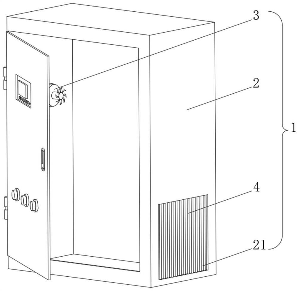
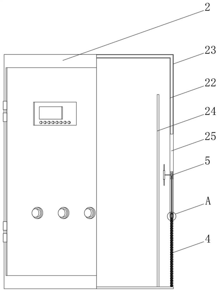
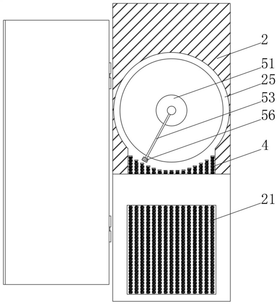
[0038] see Figure 1-4 , the present invention provides a technical solution: a dust-proof power cabinet, including a dust-proof power cabinet body 1 composed of a cabinet body 2, an exhaust fan 3, and a dust-proof mechanism 4. The right bottom of the cabinet body 2 is provided with an air intake The hole 21, the left side of the exhaust fan 3 is fixedly connected with the inside of the cabinet body 2, the cabinet body 2 includes an inner connection shell 22, the outer side of the inner connection shell 22 is provided with an outer connection shell 23, and the left side of the inner connection shell 22 is provided with The water baffle 24, the bottom of the water baffle 24 is fixedly connected with the inner wall bottom of the inner connection shell 22, the inner connection shell 22 and the outer connection shell 23 encircle the cavity 25 and the inside is provided with a pneumatic mechanism 5, and the dustproof mechanism 4 includes an anti-dust mechanism. Dust block 41, the i...

Embodiment 2

[0044] see Figure 1-5 , On the basis of Embodiment 1, the present invention provides a technical solution: the pneumatic mechanism 5 includes an inertia disk 51, and the right side of the inertia disk 51 is rotationally connected to the inside of the outer casing 23 through a receiving rod.

[0045] The left side of the inertia plate 51 is fixedly connected with a rotating rod 52 , the right end of the rotating rod 52 passes through the inertia plate 51 and is fixedly connected with the left end of the receiving rod, and the outer side of the rotating rod 52 is fixedly connected with a swing rod 53 .

[0046] The left end of the rotating rod 52 runs through the inner shell 22 and extends to the inside of the cabinet body 2. The left end of the rotating rod 52 is fixedly connected with the pneumatic disk 54, and the outer side of the pneumatic disk 54 is fixedly connected with the blade 55. The bottom end of the swing rod 53 is connected to the The blocks are fixedly attached ...

Embodiment 3

[0050] see Figure 1-6 , on the basis of Embodiment 1 and Embodiment 2, the present invention provides a technical solution: the left side of the elastic bag 42 is communicated with a one-way valve 422, and the left side of the one-way valve 422 runs through the dust-proof block 41 and extends to the The outside of the dust block 41, the right side of the elastic bag 42 is connected with the air injection block 6 through the air duct, the left side of the air injection block 6 is fixedly connected with the inside of the dustproof block 41, and the right side of the air injection block 6 is provided with an air injection hole 61.

[0051] During use, when the dust-proof rod 43 slides inside the dust-proof block 41, the elastic bag 42 is compressed by the extrusion of the dust-proof rod 43, and is restored by its own elastic force and the elastic force of the rebound block 421 at the same time. In contrast, when the dust-proof rod 43 slides inside the dust-proof block 41, the el...


PUM


Abstract

The present invention discloses a dustproof electric power cabinet which comprises a dustproof electric power cabinet body composed of a cabinet body, an exhaust fan and a dustproof mechanism, the bottom of the right side of the cabinet body is provided with an air inlet hole, the left side of the exhaust fan is fixedly connected with the interior of the cabinet body, the cabinet body comprises an inner connection shell, and the outer side of the inner connection shell is sleeved with an outer connection shell. A water stop plate is arranged on the left side of the inner connecting shell, the bottom of the water stop plate is fixedly connected with the bottom of the inner wall of the inner connecting shell, and the dustproof mechanism comprises a dustproof block. According to the dustproof electric power cabinet, the problems that in the working process of the electric power cabinet, dust in air outside the cabinet body enters the cabinet body through the heat dissipation holes and is attached to the heat dissipation holes and the electric power wires, so that the internal temperature of the electric power cabinet is increased, electric power equipment runs unstably, potential safety hazards exist, and meanwhile the electric power equipment is not damaged after being used for a long time are solved. Heat dissipation holes are easily covered by some spider webs, so that heat dissipation in the cabinet body is affected.

Description

technical field [0001] The invention relates to the field of electric power technology, in particular to a dustproof power cabinet. Background technique [0002] The switchboard (box) should be made of non-combustible materials; the production site and office with low risk of electric shock can be installed with open switchboard; in the processing workshop with high risk of electric shock or poor working environment, casting, forging, heat treatment Closed cabinets should be installed in places such as boiler rooms, carpentry rooms, etc.; in dangerous workplaces with conductive dust or flammable and explosive gases, closed or explosion-proof electrical facilities must be installed; switchboards (boxes) All electrical components, instruments, switches and lines should be arranged neatly, firmly installed and easy to operate. [0003] According to Chinese patent CN106304784B, a dust-proof power cabinet includes a cabinet body, a cabinet door is provided on the cabinet body, a...

Claims


Application Information

Patent Timeline
Patent Type & Authority Applications(China)
IPC IPC(8): H02B1/28B01D46/12B08B7/02B08B3/04B08B5/02A01M29/16H02B1/56H02B1/30
CPCH02B1/28B01D46/12A01M29/16H02B1/565H02B1/30B01D46/76B01D46/71Y02E10/72
Inventor 不公告发明人
Owner 安徽麦迪电气科技股份有限公司
Learn More