STO control and drive circuit

A driving circuit and circuit technology, applied in emergency protection circuit devices, electrical components, output power conversion devices, etc., can solve the problems of unreliability, direct and independent torque off of the motor, etc.

Pending Publication Date: 2021-06-04
JIANGSU GTAKE ELECTRIC CO LTD
View PDF0 Cites 0 Cited by
  • Summary
  • Abstract
  • Description
  • Claims
  • Application Information

AI Technical Summary

Problems solved by technology

The wave-closing signal is to block the logic signal instead of directly turning off the IGBT switch itself. This circuit seems to be more reliable and faster than the turning-off tor

Method used


Image

  • STO control and drive circuit
  • STO control and drive circuit
  • STO control and drive circuit

Examples


Embodiment Construction

[0025] The following will clearly and completely describe the technical solutions in the embodiments of the present invention with reference to the accompanying drawings in the embodiments of the present invention. Obviously, the described embodiments are only some, not all, embodiments of the present invention. Based on the embodiments of the present invention, all other embodiments obtained by persons of ordinary skill in the art without making creative efforts belong to the protection scope of the present invention.

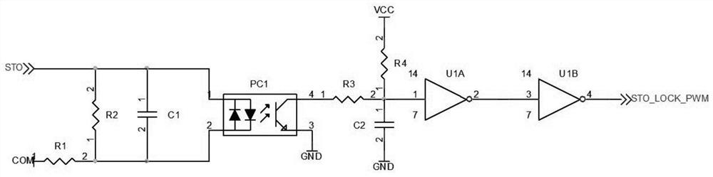
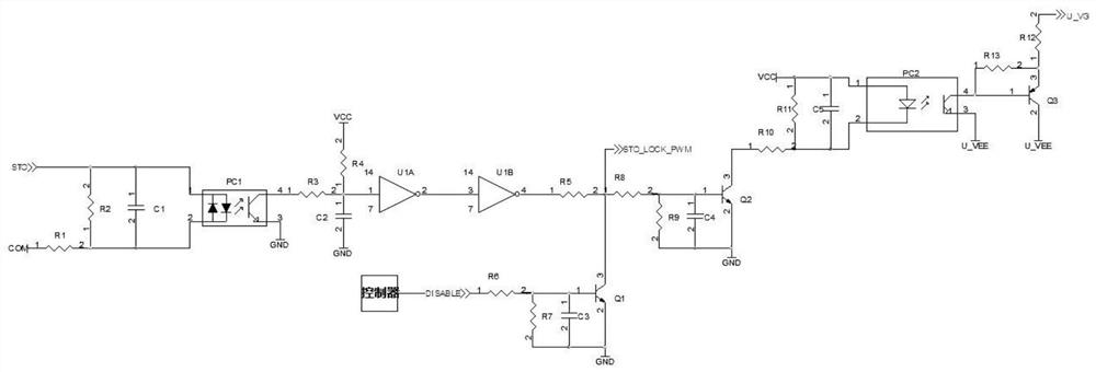
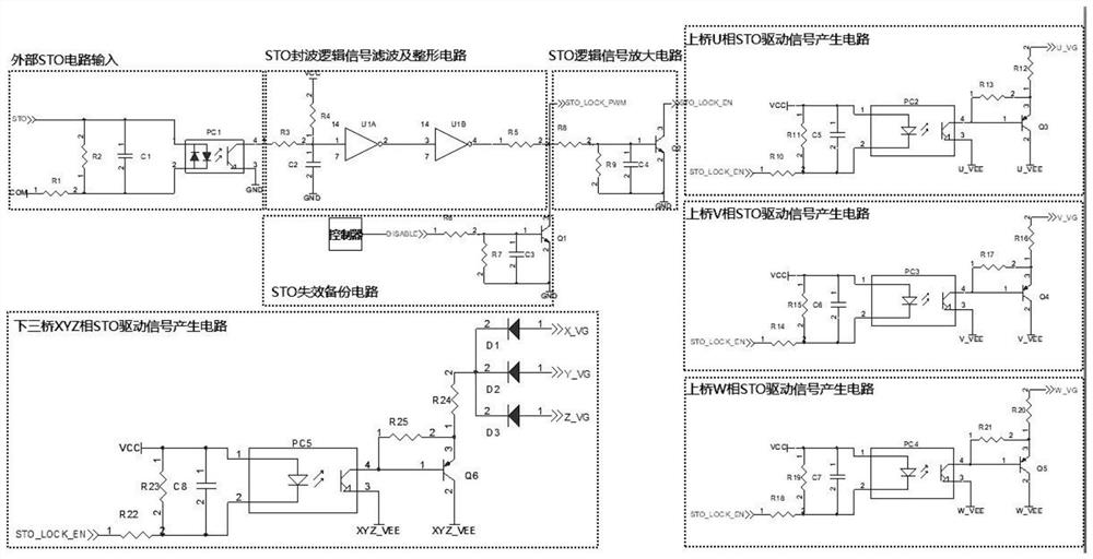
[0026] Such as Figure II Shown is a circuit diagram of the first embodiment of the most direct and effective STO control and drive circuit of the present invention. External STO circuit input, STO wave sealing logic signal filtering and shaping circuit, STO logic signal amplification circuit, STO drive signal generation circuit and STO failure backup circuit. The external STO circuit input includes a first optocoupler, a first and a second current-limiting v...


PUM


Abstract

The invention discloses an STO control and drive circuit which comprises an external STO circuit input, an STO wave sealing logic signal filtering and shaping circuit, an STO logic signal amplifying circuit, an STO drive signal generating circuit and an STO failure backup circuit. According to the invention, the turn-off torque output is realized most directly and effectively, the circuit works independently and is not limited by an inherent complex control and drive circuit of an original system, and the motor torque can be turned off timely and effectively when the motor torque output needs to be turned off timely.

Description

technical field [0001] The invention belongs to the technical field of power electronics, and in particular relates to an STO control and drive circuit. Background technique [0002] In recent years, in order to prevent accidents caused by uncontrolled starting of motors, people have put forward functional safety requirements for inverters, servo motor drivers and other products. Among them, Safe Torque Off (Safe Torque Off, STO) is such a safety function. The torque output of the motor is shut off through the output of the failed drive. The Safe Torque Off function makes the motor stop generating torque, so that the inverter , Servo motor drives become part of the safety system. In the early days, the torque output of turning off the motor was realized by switches such as contactors, and the disadvantages of this method will not be described here. [0003] At present, more circuits are used, such as Figure 1 The circuit shown is realized, and the wave sealing of the logi...

Claims


Application Information

Patent Timeline
IPC IPC(8): H02M1/08H02M1/088H02H7/08
CPCH02H7/0833H02M1/08H02M1/088
Inventor 彭小兵
Owner JIANGSU GTAKE ELECTRIC CO LTD
Why Eureka
Try Eureka