Synchronous rectification control method of flyback converter and its control module

A flyback converter and synchronous rectification technology, applied in the direction of converting DC power input to DC power output, AC power input converting to DC power output, control/regulation systems, etc. large, reduce the reliability of the device, etc., to achieve the effect of high efficiency and simple application

Active Publication Date: 2018-01-19
MORNSUN GUANGZHOU SCI & TECH
View PDF6 Cites 0 Cited by
  • Summary
  • Abstract
  • Description
  • Claims
  • Application Information

AI Technical Summary

Problems solved by technology

In the self-driving scheme, in a certain period of time, the oscillation caused by the leakage inductance of the transformer will affect the driving voltage and reduce the efficiency
At the same time, there is a delay in the drive circuit, and the synchronous rectifier SR also has a turn-on delay. When the shutdown signal is received, there is a delay until the synchronous rectifier SR is turned off, causing the output voltage to pass through the synchronization that has not been turned off in time. The rectifier tube SR supplies reverse power to the transformer winding or inductor to reduce efficiency, commonly known as reverse feeding
Backfeed not only reduces the efficiency, but also increases the voltage stress of the synchronous rectifier, thereby reducing the reliability of the device
[0016] The disadvantage of the external drive scheme is that the drive circuit is complex, detection control, timing logic, synchronous transformer, etc. are required, and currently there are very few synchronous rectification drive schemes that can adapt to CCM, which leads to non-complementary flyback active clamp converters Difficult to use external drive scheme

Method used


Image

  • Synchronous rectification control method of flyback converter and its control module
  • Synchronous rectification control method of flyback converter and its control module
  • Synchronous rectification control method of flyback converter and its control module

Examples


no. 1 example

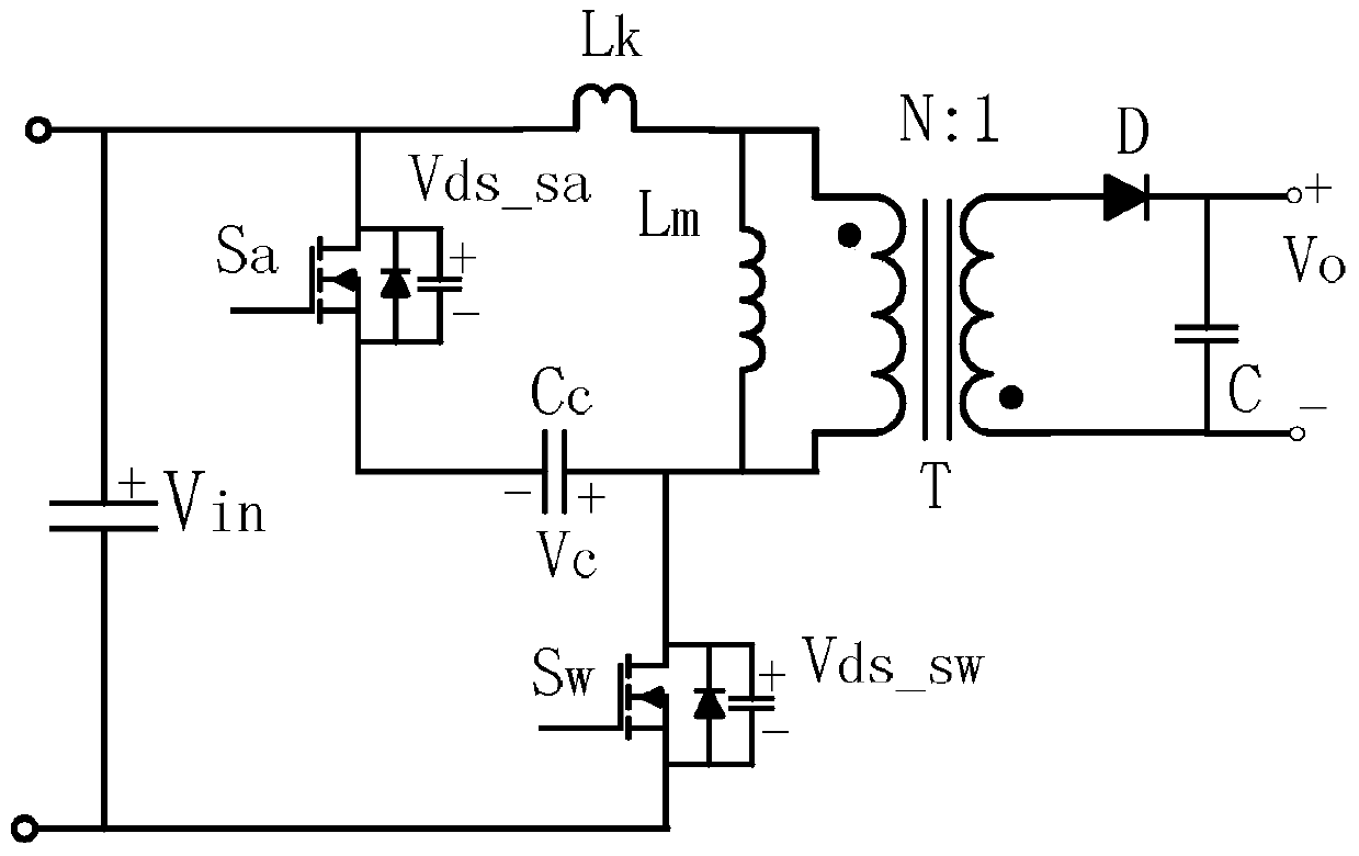
[0042] image 3 Shows the circuit schematic diagram of the flyback converter of the first embodiment of the present invention, a flyback converter, on the basis of an asymmetric flyback active clamp converter, the synchronous rectifier Q1 is applied to the synchronous The rectification circuit device also includes an integrated circuit IC1 of a synchronous rectification control module (for the sake of brevity, integrated circuit IC1, hereinafter referred to as IC1), the connection relationship of the synchronous rectification control module IC1 using the present invention is: asymmetric flyback active clamp The bit converter includes a primary side circuit and a secondary side circuit, the primary side circuit includes a clamping circuit, and the clamping circuit includes a clamping switch tube Sa and a clamping capacitor. The primary side circuit also includes a main switch tube Sw.

[0043] The secondary side circuit includes a synchronous rectifier tube Q1. The synchronous...

no. 2 example

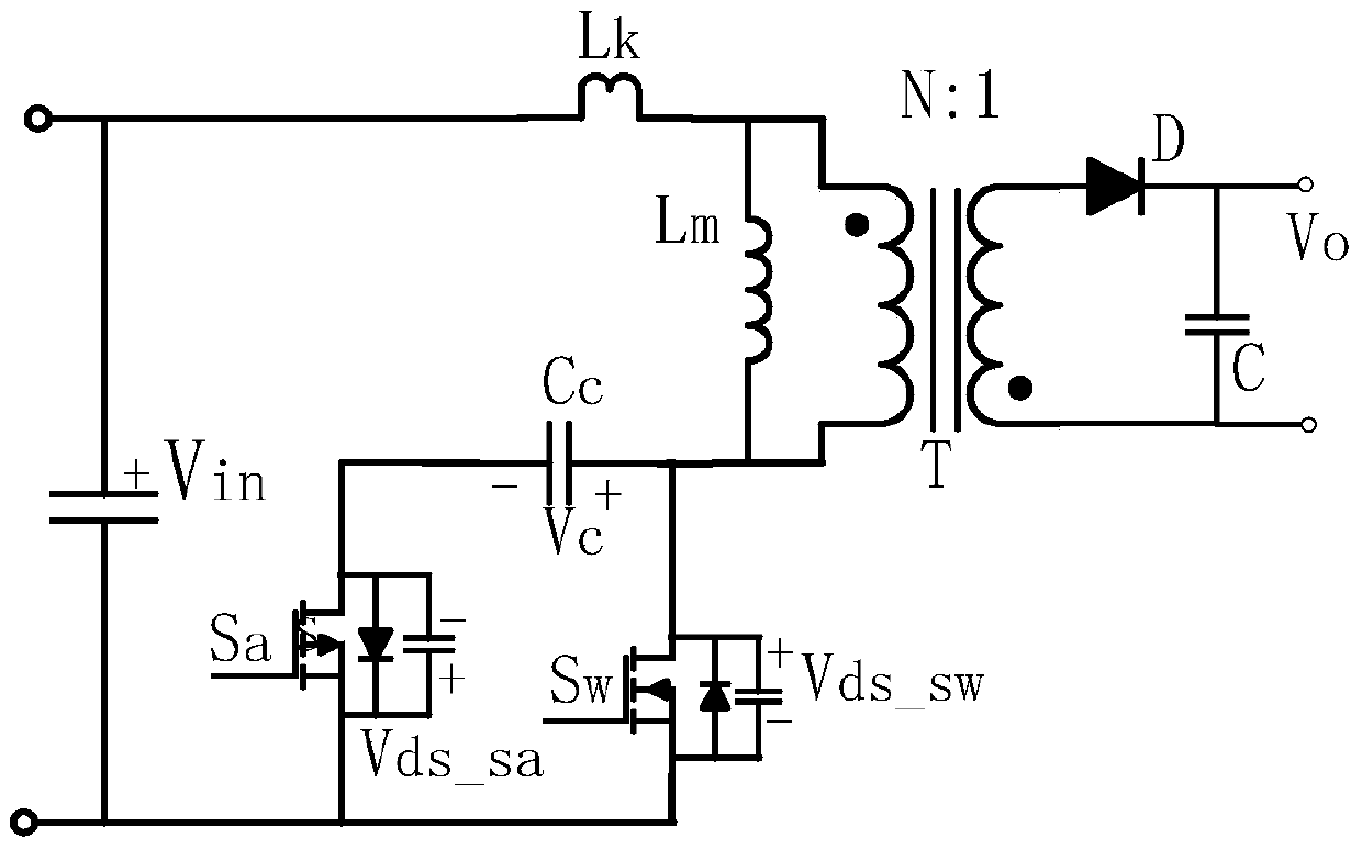
[0054] Figure 7 The schematic diagram of the second embodiment is shown, the synchronous rectifier tube Q1 is applied to the synchronous rectifier circuit device, and also includes an integrated circuit IC1, and the integrated circuit IC1 adopts the technical solution in the content of the invention to control the synchronous rectifier tube Q1. The difference from the first embodiment is that the implementation method of synchronous rectification also includes a sampling resistor Rs, which is connected in series with the synchronous rectification tube, IC1 detects the voltage Vs at both ends of the sampling resistor Rs as a control signal, and IC1 adopts the synchronous rectification of the present invention to realize method, its principle is equal to the principle of embodiment 1, and will not be repeated here, Figure 7 The device shown also achieves the object of the invention.

no. 3 example

[0056] Figure 8 The schematic diagram of the third embodiment is shown, the synchronous rectifier tube Q1 is applied to the synchronous rectifier circuit device, and also includes an integrated circuit IC1, and the integrated circuit IC1 adopts the technical solution in the content of the invention to control the synchronous rectifier tube Q1. Different from the first embodiment, the synchronous rectification implementation method also includes a current transformer Ts, the transformer Ts has a primary winding and a secondary winding, the primary winding is connected in series with the synchronous rectifier tube Q1, and IC1 detects the secondary winding of the transformer Ts The current Is of the winding is used as the control signal, and IC1 adopts the method for implementing synchronous rectification of the present invention, the principle of which is the same as that of Embodiment 1, and will not be repeated here. Figure 8 The device shown also achieves the object of the ...


PUM


Abstract

The invention particularly relates to a synchronous rectification control method for a flyback converter and a control module of the synchronous rectification control method. The synchronous rectification control method for the flyback converter is suitable for the flyback converter adopting a non-complementary active clamping control mode and mainly includes the following step of turn-off control, wherein a comparison difference value Vds is received, when the difference value Vds reflects that a current peak occurs when a first narrow pulse drive clamping tube is switched on once before a main switching tube is turned on, timekeeping is started, and a third narrow pulse Soff is transmitted when timekeeping duration reaches set duration; the step of driving, wherein a second narrow pulse and a third narrow pulse are received, switch-on, controlled by a rising edge of the second narrow pulse, of a synchronous rectification tube is output, and switch-off, controlled by a rising edge of the third narrow pulse, of the synchronous rectification tube is output. Compared with the prior art, the efficiency of the non-complementary active clamping control converter is improved further. It is unnecessary to use a synchronous transformer large in size for isolation, application is simple, and the synchronous rectification control method automatically adapts to a CCM working mode.

Description

technical field [0001] The invention relates to the field of switching converters, in particular to a synchronous rectification control method of a flyback converter and a control module thereof. Background technique [0002] With the rapid development of the field of power electronics, switching converters are used more and more widely, especially people put forward more requirements for switching converters with high power density, high reliability and small size. Generally, the traditional low-power AC / DC conversion is realized by the flyback topology, which has the advantages of simple structure and low cost; however, due to the influence of the leakage inductance of the transformer, the voltage clamping method of the main switching tube of the flyback converter includes RC buffer absorption , RCD clamp, LCD clamp and active clamp. The active clamp can not only absorb the energy of the leakage inductance and feed it back to the output terminal in the form of forward exc...

Claims


Application Information

Patent Timeline
Patent Type & Authority Patents(China)
IPC IPC(8): H02M3/335H02M7/217
CPCH02M3/33592Y02B70/10
Inventor 刘湘
Owner MORNSUN GUANGZHOU SCI & TECH
Why Eureka
Try Eureka