
Anti-collision laser cutting device with follow-up protection structure

A technology of laser cutting and protective structure, applied in laser welding equipment, manufacturing tools, metal processing equipment, etc., can solve problems such as additional loss, hard collision damage, lack of protective structure, etc., to achieve good use safety and avoid hard collision. Effect

Inactive Publication Date: 2022-05-17
XUZHOU HAITAO REFRIGERATION EQUIP
View PDF7 Cites 0 Cited by
  • Summary
  • Abstract
  • Description
  • Claims
  • Application Information

AI Technical Summary

Problems solved by technology

[0007] The purpose of the present invention is to provide an anti-collision laser cutting device with a follow-up protection structure, to solve the problem that the laser cutting device lacks an external protection structure in the background technology, and is prone to hard collision damage, and it is easy to cause additional damage when it is in a working state during a collision. loss problem

Method used


Image

  • Anti-collision laser cutting device with follow-up protection structure
  • Anti-collision laser cutting device with follow-up protection structure
  • Anti-collision laser cutting device with follow-up protection structure

Examples


Embodiment Construction

[0050] The following will clearly and completely describe the technical solutions in the embodiments of the present invention with reference to the accompanying drawings in the embodiments of the present invention. Obviously, the described embodiments are only some, not all, embodiments of the present invention. Based on the embodiments of the present invention, all other embodiments obtained by persons of ordinary skill in the art without making creative efforts belong to the protection scope of the present invention.

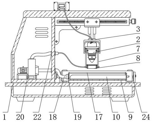
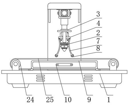
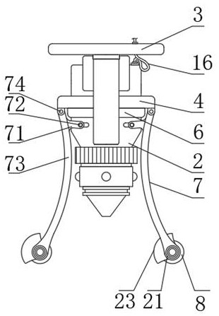
[0051] see Figure 1-Figure 8 , the present invention provides a technical solution: an anti-collision laser cutting device with a follow-up protection structure, including a cutting table 1 and a laser cutting head 2, the laser cutting head 2 is installed on the inner side of the lifting installation frame 3, and the lifting installation A movable sleeve frame 4 is arranged between the frame 3 and the laser cutting head 2, and a support spring 5 is fixedly we...


PUM


Abstract

The anti-collision laser cutting device with the follow-up protection structure comprises a cutting workbench and a laser cutting head, the laser cutting head is installed on the inner side of a lifting installation frame, and a supporting spring is fixedly welded between the lifting installation frame and the lower end of a movable sleeve frame. The laser cutting head forms a sliding lifting structure on the inner side of the movable sleeve frame, side movable frames are hinged to the left side and the right side of the movable sleeve frame, side poke rods are arranged at the attaching positions of the side movable frames and the laser cutting head, and deflection structures of the side movable frames form a synchronous adjusting structure for a lifting structure of the laser cutting head through the side poke rods. According to the laser cutting head, a side edge protection structure is formed for the laser cutting head through the side edge installation structure of the side movable frame, meanwhile, a linkage adjustment installation structure is formed between the side poke rod of the side movable frame and the laser cutting head, flexible disassembly and assembly of the laser cutting head are facilitated, and meanwhile hard collision of a laser cutting head body is effectively avoided.

Description

technical field [0001] The invention relates to the technical field of laser cutting, in particular to an anti-collision laser cutting device with a follow-up protection structure. Background technique [0002] Laser cutting mainly uses the lens inside the lens to focus to produce a high-power laser beam focus to irradiate the surface of the cutting plate, which generates extremely high temperature to melt the local material, and at the same time cooperates with the coaxial high-pressure airflow of the laser beam to blow away the slag, thereby forming a section on the surface of the plate. Cutting, compared with cold cutting, laser cutting saves the processing cost of the tool and reduces the cost of subsequent processing, which is widely used in some cutting processing occasions; [0003] However, when the existing laser cutting device is in use, there are certain problems: [0004] 1. The laser cutting head lacks an external protective structure. During the cutting proces...

Claims


Application Information

Patent Timeline
Patent Type & Authority Applications(China)
IPC IPC(8): B23K26/38B23K26/70B23K26/142
CPCB23K26/38B23K26/702B23K26/142Y02P70/10
Inventor 张逢娣王海涛
Owner XUZHOU HAITAO REFRIGERATION EQUIP
Learn More