Pressure control type catheter

A urinary catheter, the first-class technology, applied in the direction of catheter, balloon catheter, etc., can solve the problems of bladder and bladder bleeding, bladder unfavorable and so on

Pending Publication Date: 2021-06-08
佑成(杭州)医疗器械有限公司
View PDF0 Cites 0 Cited by
  • Summary
  • Abstract
  • Description
  • Claims
  • Application Information

AI Technical Summary

Problems solved by technology

[0005] The purpose of the present invention is to solve the problem in the prior art that bladder pressure is easily caused by a sudden drop in bladder pressure due to too much urine that is continuously drained out without resistance when the catheter is used to

Method used


Image

  • Pressure control type catheter
  • Pressure control type catheter
  • Pressure control type catheter

Examples


Embodiment 1

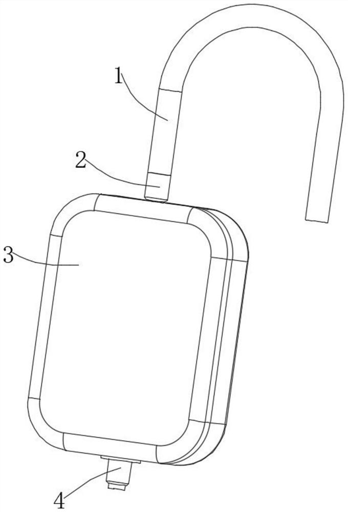
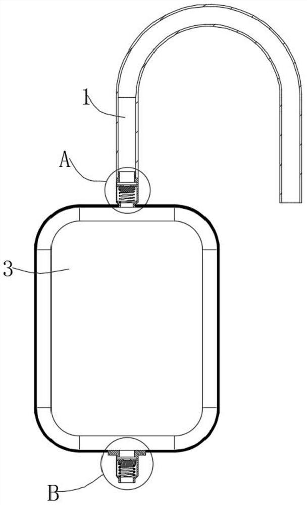
[0038] The end of the catheter 1 is connected with a one-way valve 2, the bottom of the one-way valve 2 is provided with a water bag 3 connected thereto, and the bottom of the water bag 3 is connected with a resistance one-way valve 4, and the one-way valve 2 and the resistance one-way valve 4 can It is the same type of one-way valve, that is, the second valve body 401 is provided with a one-way resistance mechanism 5 at the bottom of the second flow hole 405. The one-way resistance mechanism 5 includes an outer ring 501, a connecting strip 502, an inner ring 503, and the outer ring 501 is fixedly connected to the bottom outside the second flow hole 405, the inner ring 503 is located at the bottom of the second flow hole 405, and the inner ring 503 and the second flow hole 405 are connected flexibly, the one-way valve 2 and the resistance one-way valve 4. It can be a valve-like one-way valve, or a valve-like one-way valve. The valve-like one-way valve or the valve-like one-way ...

Embodiment 2

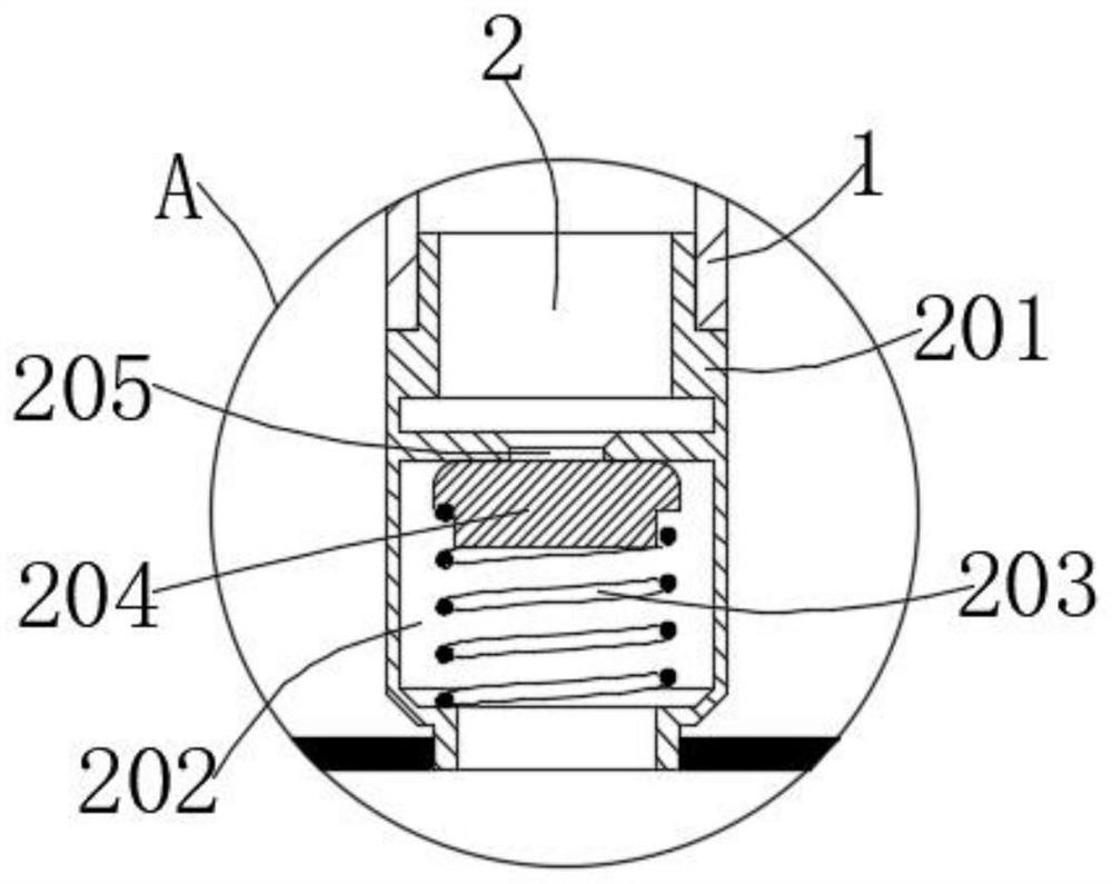
[0040] The end of the urinary catheter 1 is connected with a one-way valve 2, the bottom of the one-way valve 2 is provided with a water bag 3 communicating with it, the bottom of the water bag 3 is connected with a resistance one-way valve 4, and the one-way valve 2 includes a first valve body 201, The first valve cavity 202, the first spring 203, the first valve core 204, and the first flow hole 205, the first valve body 201 is provided with the first valve cavity 202, and the bottom end of the first valve cavity 202 is fixed with a first Spring 203, the top of the first spring 203 is fixed with the first valve core 204 matching with the first flow hole 205, the resistance check valve 4 includes a second valve body 401, a second valve chamber 402, a second spring 403, a second The second valve core 404, the second flow hole 405, the second valve body 401 is provided with a second valve cavity 402, the bottom of the second valve cavity 402 is fixed with a second spring 403, an...


PUM


Abstract

The invention discloses a pressure control type catheter, which relates to the technical field of medical equipment. The pressure control type catheter comprises a catheter, the tail end of the catheter is connected with a one-way valve, the bottom of the one-way valve is fixedly provided with a water bag communicated with the one-way valve, and the bottom of the water bag is connected with a resistance one-way valve. The front end of the catheter is inserted into the bladder, the tail end of the catheter is connected with the water bag through the one-way valve, when urine exists in the bladder, the overall pressure in the bladder is increased, the urine is squeezed by the pressure, a squeezing acting force is generated on the one-way valve, then the urine flows into the water bag through the catheter, when there is more urine in the bladder, the water bag can be rapidly filled with urine through the catheter, a worker judges whether the urination speed needs to be increased or not according to the filling degree of the urine in the water bag and the opening condition of the resistance one-way valve, the worker can manually squeeze the water bag to increase the pressure in the water bag, then the urine pushes the resistance one-way valve to be opened greatly, and the urine discharge speed is increased.

Description

technical field [0001] The invention relates to the technical field of medical equipment, in particular to a pressure-controlling urinary catheter. Background technique [0002] A urinary catheter is a tube that is inserted into the bladder from the urethra to drain urine. It is a pipeline made of natural rubber, silicone rubber, or polyvinyl chloride (PVC). After the catheter is inserted into the bladder, there is a balloon near the tip of the catheter to fix the catheter in the bladder so that it does not come out easily, and the drainage tube is connected to a urine bag to collect urine. [0003] When various reasons cause the patient's bladder to be full and unable to urinate, or to prevent overfilling of the bladder and making it difficult to urinate, it is necessary to use a catheter to solve such problems. Most intracavitary operations in urology are performed on the basis of fluid flushing. When a large amount of fluid enters the urinary system cavity, the pressure ...

Claims


Application Information

Patent Timeline
IPC IPC(8): A61M25/10A61M25/00
CPCA61M25/10A61M25/0017A61M25/0021A61M25/0043A61M25/0075A61M2025/0076
Inventor 孔咪咪
Owner 佑成(杭州)医疗器械有限公司
Why Eureka
Try Eureka