Grinding mechanism for track welding spots

A technology of grinding mechanism and welding point, which is applied to machine tools, grinding machines, grinding workpiece supports and other directions suitable for grinding workpiece edges, which can solve the complicated operation of orbital welding grinding equipment mechanism, low working efficiency of orbital welding points, high precision and poor accuracy. Poor stability, etc.

Inactive Publication Date: 2021-06-08
叶洪娟
View PDF0 Cites 5 Cited by
  • Summary
  • Abstract
  • Description
  • Claims
  • Application Information

AI Technical Summary

Problems solved by technology

[0005] The invention provides a grinding mechanism for track solder joints, which does not need to move the grinding mechanism as a whole so that the grinding sheet on it can move along the track of the curved surface of the track, the operation is simple, convenient, time-saving and labor-saving, and the accuracy and stability are relatively high. High advantages, solve the problem that due to the curved surface structure design of the track surface, when the existing track welding and grinding equipment mechanism grinds its welding points, it needs to swing the grinding mechanism as a whole so that the grinding sheet on it can follow the curved surface of the track surface The orbital grinding operation makes the operation of the orbital welding and grinding equipment mechanism more cumbersome during use, which consumes a lot of physical strength for the operator, and the accuracy and stability are poor, and the work efficiency for orbital welding point grinding is relatively low. The problem

Method used


Image

  • Grinding mechanism for track welding spots
  • Grinding mechanism for track welding spots
  • Grinding mechanism for track welding spots

Examples


Embodiment Construction

[0022] The technical solutions in the embodiments of the present invention will be clearly and completely described below with reference to the accompanying drawings in the embodiments of the present invention. Obviously, the described embodiments are only a part of the embodiments of the present invention, but not all of the embodiments. Based on the embodiments of the present invention, all other embodiments obtained by those of ordinary skill in the art without creative efforts shall fall within the protection scope of the present invention.

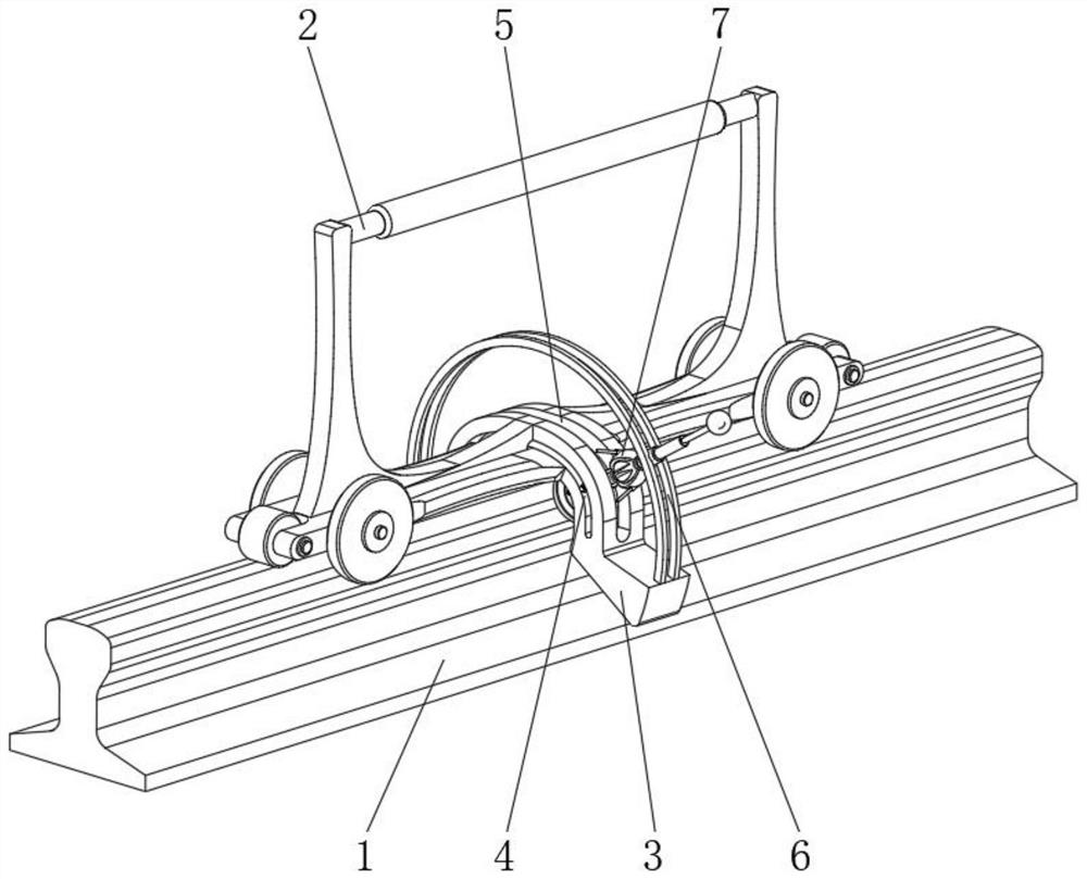
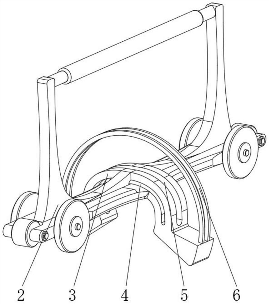
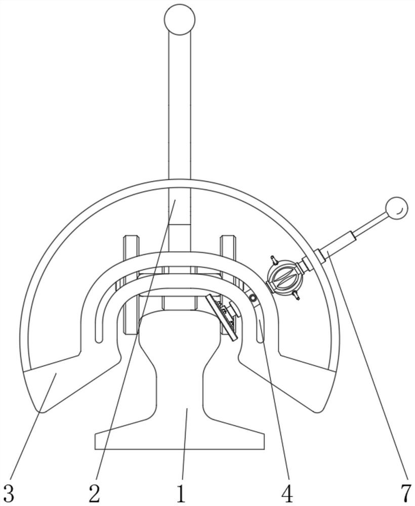
[0023] see Figure 1-4 , a grinding mechanism for track solder joints, comprising a rail 1, a walking bracket 2 is clamped on the surface of the rail 1, a track slide plate 3 is provided at the bottom end of the inner cavity of the track slide plate 3, and left and right sides are provided inside the track slide plate 3. The penetrating track chute 4, and the inside of the track skateboard 3 is provided with a fixed chute 5 that penet...


PUM


Abstract

The invention relates to the technical field of track welding and grinding equipment, and discloses a grinding mechanism for track welding spots. The grinding mechanism comprises a steel rail, wherein a walking bracket is clamped on the surface of the steel rail, a track sliding plate is arranged at the bottom end of an inner cavity of the walking bracket, a track sliding groove which is through left and right is formed in the track sliding plate, a vertically-through fixed sliding groove is formed in the track sliding plate, and a grinding mechanism body is movably connected into the track sliding plate in a sleeved mode. According to the grinding mechanism for the track welding spots, the track sliding plate, the track sliding groove and the fixed sliding groove are arranged, so that the grinding mechanism can drive a grinding disc on the grinding mechanism to conduct movable grinding operation on the surface of the steel rail along the track of the track sliding groove; and compared with an existing track grinding mechanism, the whole grinding mechanism does not need to be moved when the welding spots on the steel rail are ground, operation of the grinding mechanism is greatly simplified, time and labor are saved when the grinding mechanism is used, and controllability and stability are relatively high.

Description

technical field [0001] The invention relates to the technical field of orbital welding and grinding equipment, in particular to a grinding mechanism for orbital welding spots. Background technique [0002] The laying of railway rails is to weld several sections of rails to form a whole track, but when two adjacent sets of rails are welded, due to welding technology, the surface of the rails is welded. For the safe and stable operation of the track, the surface of the track must be kept flat. Therefore, after the track is welded, it is necessary to polish the welding points to ensure the smoothness of the track. [0003] However, due to the curved surface structure design of the track surface, when the existing track welding and grinding equipment mechanism is grinding its welding points, it needs to swing the grinding mechanism as a whole so that the grinding sheet on the track surface can be polished along the curved track of the track surface , As a result, the operation ...

Claims


Application Information

Patent Timeline
Patent Type & Authority Applications(China)
IPC IPC(8): B24B9/04B24B41/04B24B41/06B24B47/12B24B47/20B24B47/22
CPCB24B9/04B24B41/04B24B41/06B24B47/12B24B47/20B24B47/22
Inventor 叶洪娟
Owner 叶洪娟
Why Eureka
Try Eureka