Hardware polishing machining dust treatment equipment

A dust treatment and equipment technology, which is applied in the field of hardware polishing dust treatment equipment, can solve problems such as difficult cleaning, falling off, environmental pollution, etc., and achieve the effect of avoiding floating everywhere

Inactive Publication Date: 2021-06-08
上海曰茶贸易有限公司
View PDF0 Cites 0 Cited by
  • Summary
  • Abstract
  • Description
  • Claims
  • Application Information

AI Technical Summary

Problems solved by technology

[0003] Based on the inventor's discovery above, the existing a kind of metal polishing processing dust treatment equipment mainly has the following disadvantages, for example: when polishing a workpiece with rust marks, the grinding wheel rubs against the end face of the workpiece, so that The rust marks on the workpiece will fall off and form fine dust, resulting in a large amount of dust when the workpiece is polished, causing the dust to be scattered all over the place and not easy to clean up, and will also pollute the environment

Method used


Image

  • Hardware polishing machining dust treatment equipment
  • Hardware polishing machining dust treatment equipment
  • Hardware polishing machining dust treatment equipment

Examples


Embodiment 1

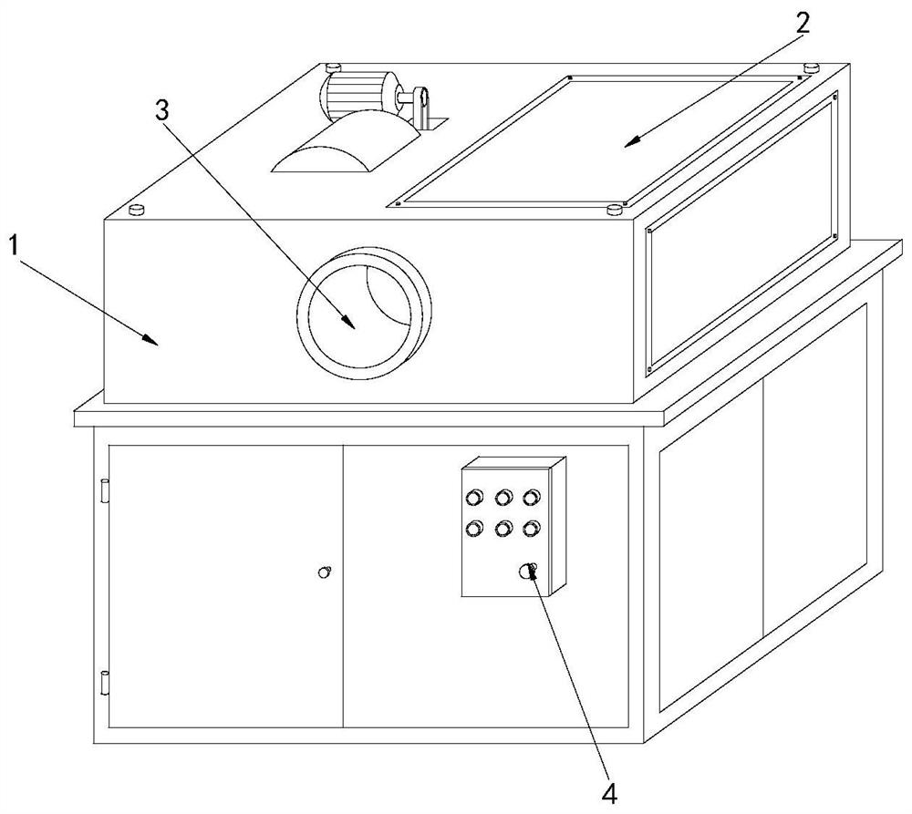
[0026] Example 1: Please refer to Figure 1-Figure 5 , the specific embodiments of the present invention are as follows:

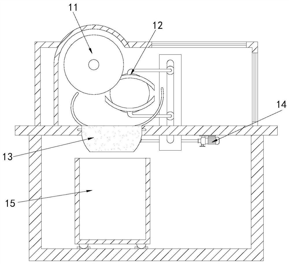
[0027] Its structure includes a main body 1, a glass plate 2, a feed port 3, and a control panel 4, the top of the main body 1 is provided with a glass plate 2, the feed port 3 is arranged at the front end of the main body 1, and the control panel 4 is located at The bottom of the front end of the main body 1. The main body 1 includes a grinding wheel 11, a clamping block 12, a material guide device 13, an air pump 14, and a collection box 15. The grinding wheel 11 is arranged on the inner upper end of the main body 1. The clamping The block 12 is positioned at the side end of the grinding wheel 11, the material guide 13 is installed directly below the grinding wheel 11, and the collection box 15 is arranged at the bottom of the main body 1, and the vertical position is flush with the grinding wheel 11.

[0028] Described material guide device 13 comprise...

Embodiment 2

[0032] Example 2: Please refer to Figure 6-Figure 8 , the specific embodiments of the present invention are as follows:

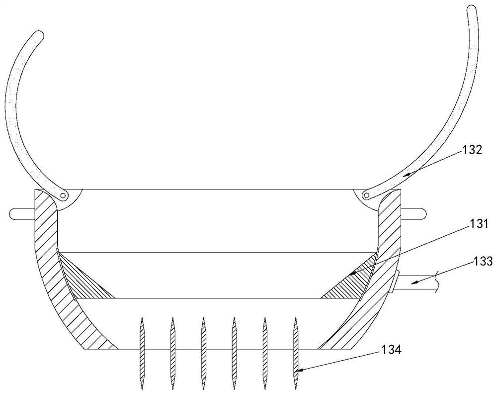
[0033] The suction device 131 includes a circulation groove b1, an air storage tank b2, an air suction hole b3, and a vent pipe b4. There are two flow grooves b1 located at both ends of the suction device 131 respectively. The groove b2 is arranged at the side end of the circulation groove b1, the air suction hole b3 is provided with more than four, and is arranged around the side end of the gas storage tank b2, and the ventilation pipe b4 connects the bottom of the two gas storage tanks b2 The air suction hole b3 communicates with the bottom end of the circulation tank b1, which facilitates air suction through the air pump 14 and allows the air flow to flow in the air storage tank b2.

[0034]The air suction hole b3 includes an air collection block b31, an air inlet b32, a filter screen b33, a wind deflector b34, and an anti-backflow block b35. The air c...


PUM


Abstract

The invention discloses hardware polishing machining dust treatment equipment which structurally comprises a main body, a glass plate, a feeding port and a control panel. The glass plate is arranged at the top end of the main body, the feeding port is formed in the front end of the main body, the control panel is located at the bottom of the front end of the main body, and the main body comprises a grinding wheel, a clamping block, a material guiding device, an air pump and a material collecting box; and the material guiding device comprises a material sucking device, material guiding plates, an air inlet pipe and a discharging piece, each material guiding plate comprises a material guiding body, a rewinding spring, a material guiding groove, a material passing groove and a material guiding block, and each material guiding block comprises a supporting plate, a guiding piece, a buffering pad, an empty groove and a rebounding piece. According to the hardware polishing machining dust treatment equipment, the two material guiding plates at the top end of the material guiding device are used for guiding dust, and then the dust is vertically guided downwards through the discharging piece, so that the dust can directly enter the material collecting box, the dust can be collected in a centralized manner, the situation that the dust is scattered on the ground and is not easy to clean is avoided, and it can be guaranteed that workers cannot inhale the dust.

Description

technical field [0001] The invention relates to the field of surface polishing processing in hardware production, in particular to a metal polishing processing dust treatment equipment. Background technique [0002] Polishing operation is an important process step in many production processes. Most of the metal products need to be polished to improve the appearance of beauty. When the polishing machine is working, the motor drives the grinding wheel to rotate, and then the processed workpiece It rubs against the end surface of the grinding wheel to achieve a polishing effect on the workpiece. [0003] Based on the inventors' discovery above, the existing dust processing equipment for metal polishing processing mainly has the following disadvantages, for example: when polishing a workpiece with rust marks, the grinding wheel rubs against the end face of the workpiece, so that The rust marks on the workpiece will fall off and form fine dust, which will cause a large amount of...

Claims


Application Information

Patent Timeline
Patent Type & Authority Applications(China)
IPC IPC(8): B24B29/02B24B27/033B24B55/06B24B55/12
CPCB24B27/033B24B29/02B24B55/06B24B55/12
Inventor 王辉
Owner 上海曰茶贸易有限公司
Why Eureka
Try Eureka