
Drawing cutting device for mechanical automation specialty

A professional and drawing technology, applied in the field of mechanical automation professional drawing cutting devices, can solve the problems of drawings affecting the cutting effect, unable to fix the drawings, uneven cutting surface, etc., so as to improve the cutting effect, improve the flatness and cut flat surface effect

Pending Publication Date: 2021-06-08
JIUQUAN VOCATIONAL & TECHN COLLEGE
View PDF5 Cites 0 Cited by
  • Summary
  • Abstract
  • Description
  • Claims
  • Application Information

AI Technical Summary

Problems solved by technology

[0004] The commonly used drawing cutting devices are all vertical and downward straight cutting methods. When cutting multiple drawings at the same time, the power required by the cutter is relatively large. At the same time, the cutting surface is uneven and the cutting effect is not good;
[0005] The drawing cannot be fixed well, resulting in the displacement of the drawing during cutting and affecting the cutting effect

Method used


Image

  • Drawing cutting device for mechanical automation specialty
  • Drawing cutting device for mechanical automation specialty
  • Drawing cutting device for mechanical automation specialty

Examples


Embodiment Construction

[0028] In order to make the object, technical solution and advantages of the present invention clearer, the present invention will be further described in detail below in conjunction with the accompanying drawings and embodiments. It should be understood that the specific embodiments described here are only used to explain the present invention, not to limit the present invention.

[0029] In describing the present invention, it should be understood that the terms "length", "width", "upper", "lower", "front", "rear", "left", "right", "vertical", The orientation or positional relationship indicated by "horizontal", "top", "bottom", "inner", "outer", etc. are based on the orientation or positional relationship shown in the drawings, and are only for the convenience of describing the present invention and simplifying the description, rather than Nothing indicating or implying that a referenced device or element must have a particular orientation, be constructed, and operate in a ...


PUM


Abstract

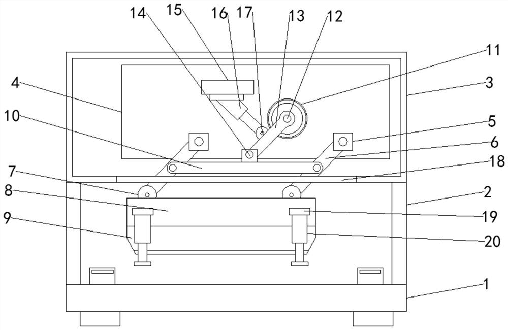
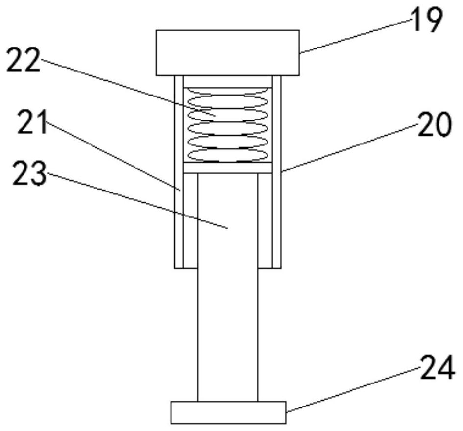
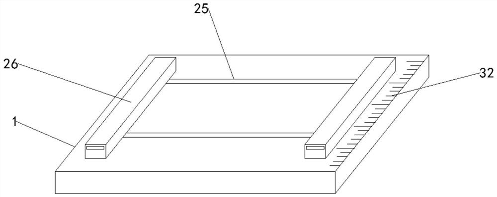
The invention belongs to the technical field of cutting, and particularly relates to a drawing cutting device for mechanical automation specialty. The device comprises a cutting table, wherein supporting rods are fixedly connected to the four corners of the upper end face of the cutting table, a mounting box is fixedly connected to the upper end faces of the four supporting rods, and a mounting plate is fixedly connected to the back of the inner wall of the mounting box. A cutter holder at the bottom performs the same right lower movement, so that the cutter is driven to move downwards and move rightwards at the same time, a drawing at the upper end of the cutting table is obliquely cut, an air cylinder shrinks after cutting is completed, and the cutter can be driven to retract, so that compared with vertical tangent cutting, the flatness of the cutting face is improved, more labor is saved, and the drawing cutting effect is improved; and the device solves the problems that according to an existing drawing cutting device, generally used drawing cutting devices are all in a vertically-downward straight cutting mode, and when a plurality of drawings are cut at the same time, power needed by the cutter is large, meanwhile, the cutting face is uneven, the cutting effect is poor, the drawings cannot be well fixed, and the cutting effect is affected due to displacement of the drawings in the cutting process.

Description

technical field [0001] The invention relates to the technical field of cutting, in particular to a blueprint cutting device for mechanical automation. Background technique [0002] Mechanical manufacturing and its automation is a subject that studies mechanical manufacturing theory, manufacturing technology, automated manufacturing systems and advanced manufacturing models. Mechanical drawing is one of the basic compulsory courses offered by mechanical and related majors in most colleges and universities. Mechanical drawing is a subject that uses drawings to accurately represent the structural shape, size, working principle and technical requirements of machinery. Composed of graphics, symbols, text and numbers, drawings are technical documents expressing design intentions and manufacturing requirements as well as exchanging experience. They are often called the language of the engineering world. Because the purchase cost of large-scale drawings is relatively low, the The f...

Claims


Application Information

Patent Timeline
Patent Type & Authority Applications(China)
IPC IPC(8): B26D1/06B26D5/12B26D7/02B26D7/28
CPCB26D1/06B26D5/12B26D7/025B26D7/28
Inventor 王军张秀王建朝
Owner JIUQUAN VOCATIONAL & TECHN COLLEGE
Learn More