Waste plastic recycling equipment

A technology of recycling equipment and waste plastics, which is applied in the field of waste plastics recycling, can solve the problems of workers inhaling large dust, unfavorable environmental protection, and reduced performance, so as to achieve the effects of benefiting human health, promoting crushing efficiency, and improving crushing efficiency

Inactive Publication Date: 2021-06-08
石岩嘎
View PDF0 Cites 1 Cited by
  • Summary
  • Abstract
  • Description
  • Claims
  • Application Information

AI Technical Summary

Problems solved by technology

[0005] Aiming at the deficiencies of the prior art, the present invention provides a waste plastic recycling equipment, which solves the problem that the traditional waste plastic shredder will produce a large amount of dust during the crushing process, and has no function of dust removal, so that the dust will fly and the staff will inhale it. A large amount of dust is not conducive to human health. At the same time, a large amount of dust is discharged into the atmosphere, which also pollutes the air, which is not conducive to environmental protection and reduces the problem of performance.

Method used


Image

  • Waste plastic recycling equipment
  • Waste plastic recycling equipment
  • Waste plastic recycling equipment

Examples


Embodiment example 1

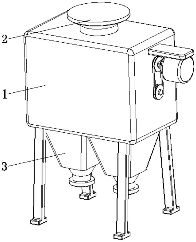
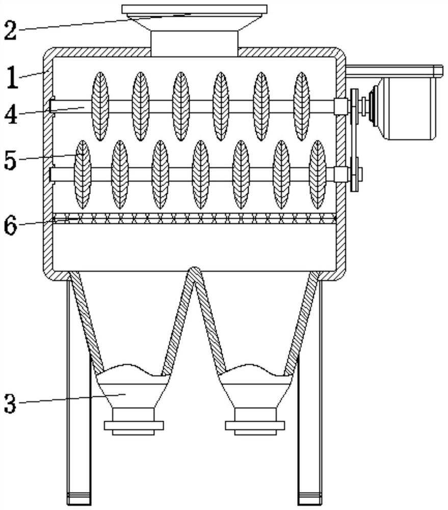
[0035] see Figure 1-7 , the present invention provides a technical solution: a waste plastic recycling equipment, including a crushing chamber 1, a feed hopper 2, and a discharge port 3, the feed hopper 2 is fixed at the top center of the crushing chamber 1, and the feed hopper 2 and The crushing chambers 1 are connected, and the discharge port 3 is set at the bottom center of the crushing chamber 1;

[0036] The interior of the crushing chamber 1 is provided with a driving shaft 4, a crushing device 5, and a screen 6, and the driving shaft 4 is rotatably connected between the corresponding two sides of the crushing chamber 1 and is close to the position of the feed hopper 2, and the crushing device 5 is fixed on On the surface of the drive shaft 4, the crushing device 5 is evenly distributed on the surface of the drive shaft 4 and arranged staggered up and down. The screen 6 is fixed on the inner wall of the crushing chamber 1 and is close to the position of the crushing dev...

Embodiment example 2

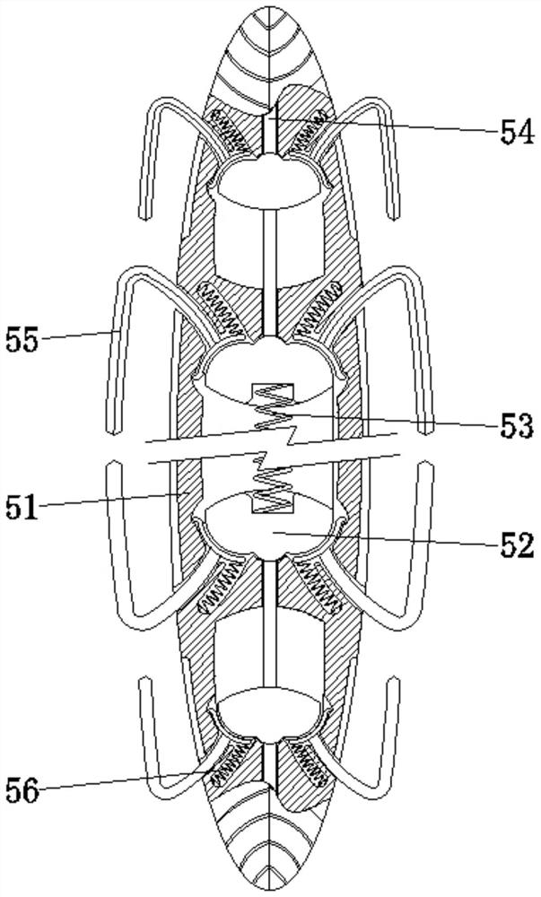
[0042] The auxiliary crushing knife device 55 is provided with a cutter body 551, a top plate 552, a blade slope 553, and a knife groove 554. The cutter body 551 is slidingly connected with the main crushing tooth 51. The top plate 552 is located inside the main crushing tooth 51 and is connected to the end of the cutter body 551 The blade slope 553 is provided on both sides corresponding to the surface of the cutter body 551, the knife groove 554 is provided on the surface of the blade body 551 and is located at the position of the blade slope 553, and the auxiliary crushing knife device 55 is easily pushed out by using the top plate 552 , is conducive to improving the crushing efficiency, the entire cutter body 551 can increase the crushing area of ​​waste plastics, and the blade bevel 553 and knife groove 554 reduce the stress area, thereby making the crushing effect better.

[0043] When in use, first pour waste plastics from the feed hopper 2 into the crushing chamber 1, a...


PUM


Abstract

The invention discloses waste plastic recycling equipment, and relates to the technical field of waste plastic recycling. The waste plastic recycling equipment comprises a crushing chamber, a feeding hopper and discharging ports. The feeding hopper is fixed to the center of the top of the crushing chamber and communicated with the crushing chamber, and the discharging ports are formed in the center of the bottom of the crushing chamber. Driving rotating shafts are rotatably connected to the position, close to the feeding hopper, between the two corresponding sides in the crushing chamber, crushing devices are fixed to the surfaces of the driving rotating shafts, the crushing devices are evenly distributed on the surfaces of the driving rotating shafts and arranged in an up-down staggered mode, and a screen is fixed to the position, close to the crushing devices, of the inner wall of the crushing chamber. According to the waste plastic recycling equipment, the purposes of dust removal and rapid crushing are achieved, dust can be removed in time, dust diffusion is reduced, the human body inhalation amount is reduced, human health is facilitated, pollution to the atmosphere is reduced, meanwhile, crushing is rapid and thorough, and the crushing efficiency and the use performance are improved.

Description

technical field [0001] The invention relates to the technical field of recycling waste plastics, in particular to recycling equipment for waste plastics. Background technique [0002] Plastic refers to the plastic (flexible) material processed and formed with high molecular weight synthetic resin as the main component, adding appropriate additives, such as plasticizers, stabilizers, antioxidants, flame retardants, colorants, etc., or cured Rigid material formed by cross-linking. But the "white pollution" caused by waste plastics is becoming more and more serious. Waste plastics have been used in China for a long time, and a complete industrial chain has been formed for their recycling and sorting. However, the overall development level is still far behind that of advanced countries in the world. On the one hand, due to the wide range of sources of recycled plastics, the quality varies. The performance difference between batches is also relatively large, resulting in poor q...

Claims


Application Information

Patent Timeline
Patent Type & Authority Applications(China)
IPC IPC(8): B29B17/04B29B17/02B01D47/06
CPCB01D47/06B29B17/02B29B17/04B29B2017/0203B29B2017/0224B29B2017/044B29B2017/0476Y02W30/52Y02W30/62
Inventor 不公告发明人
Owner 石岩嘎
Why Eureka
Try Eureka