
New energy automobile controller integration device based on V-shaped groove heat dissipation

A technology for new energy vehicles and integrated devices, applied in the directions of mounting board safety devices, circuit layout on support structures, vehicle components, etc., can solve the problems of difficult assembly methods, unfavorable cost control, and reduced PCB tile area, etc. To achieve the effect of being conducive to heat dissipation, strong integration, and reducing PCB area

Active Publication Date: 2021-06-08
SHENZHEN GAOKERUN ELECTRONICS CO LTD
View PDF5 Cites 0 Cited by
  • Summary
  • Abstract
  • Description
  • Claims
  • Application Information

AI Technical Summary

Problems solved by technology

[0003] The high-power MOS tube inside the new energy vehicle controller is a component that generates a relatively large amount of heat. How to ensure that the heat is dissipated to the maximum extent under the condition that the product functions are intact is a design link worth thinking about; currently, the industry generally adopts The best solution is to tile the MOS on the radiator. This conventional solution does not reduce the tile area of ​​the PCB board, which is not conducive to cost control, and the heat directly acts on the PCB board, which may affect the performance of other components. It is also a test for the Tg value of the PCB board; if the MOS tube does not adopt the plan of flat pressing, then the assembly method is a relatively difficult design point

Method used


Image

  • New energy automobile controller integration device based on V-shaped groove heat dissipation
  • New energy automobile controller integration device based on V-shaped groove heat dissipation
  • New energy automobile controller integration device based on V-shaped groove heat dissipation

Examples


Embodiment Construction

[0021] The following will clearly and completely describe the technical solutions in the embodiments of the present invention with reference to the accompanying drawings in the embodiments of the present invention. Obviously, the described embodiments are only some, not all, embodiments of the present invention. Based on the embodiments of the present invention, all other embodiments obtained by persons of ordinary skill in the art without making creative efforts belong to the protection scope of the present invention.

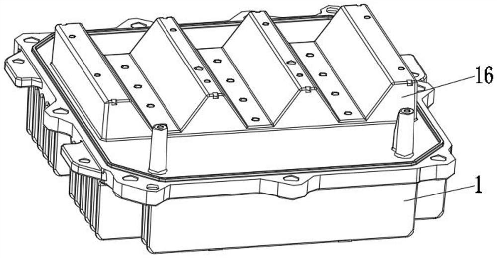
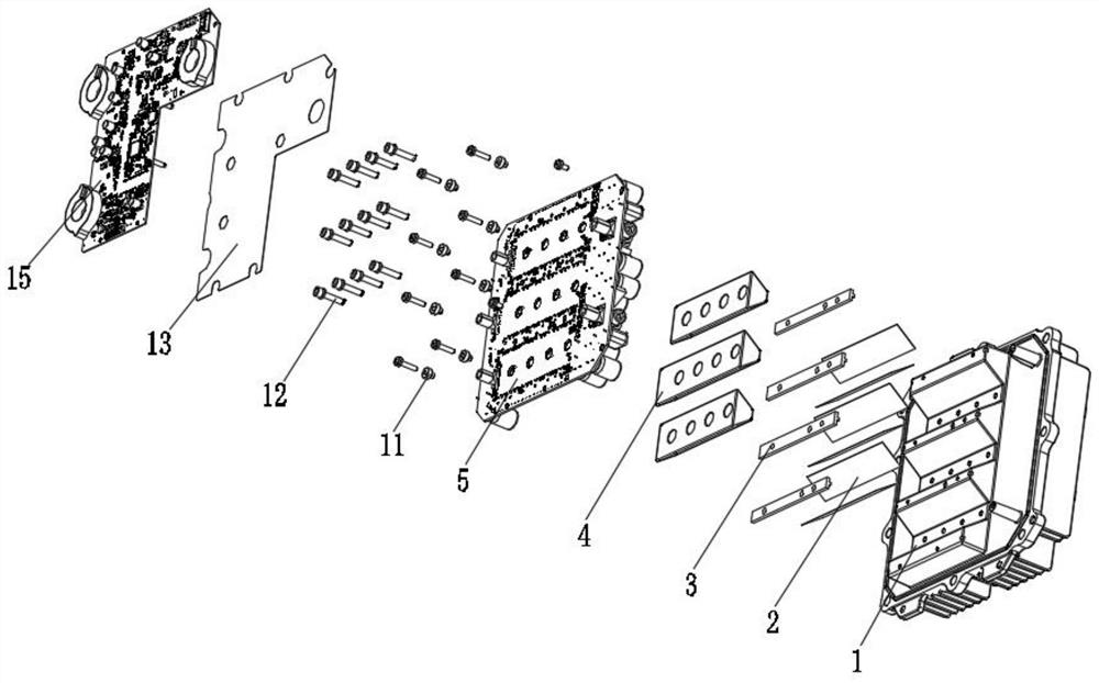
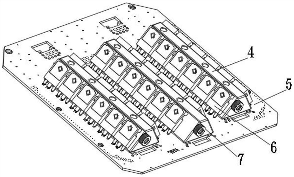
[0022] see Figure 1-7 , the present invention provides a technical solution: a new energy vehicle controller integrated device based on V-groove heat dissipation, including V-groove radiator 1, phase change film 2, PCB backing plate 3, bakelite pressing block 4, power Capacitor plate 5, wiring copper plate 6, MOS tube 7, connection hole 8, wiring copper nose 9, first screw 10, insulating particle 11, second screw 12, insulating sheet 13, screw assembly hole 1...


PUM


Abstract

The invention discloses a new energy automobile controller integration device based on V-shaped groove heat dissipation. The device comprises a V-shaped groove radiator, a phase change film, a PCB base plate, a bakelite pressing block, a power capacitor plate, a wiring copper plate, an MOS tube, a connecting hole, a wiring copper nose, a first screw, an insulating particle, a second screw, an insulating sheet, a screw assembly hole, a control panel and a cover plate. A phase change film is distributed and connected to the outer wall of the top end of the V-shaped groove radiator in an attached mode, and the PCB base plate is connected to the outer wall of the top end, located on one side of the phase change film, of the V-shaped groove radiator in a clamped mode. According to the new energy automobile controller integration device, the MOS tube is not in contact with the PCB except for the pin so that the influence of MOS heat on other elements is effectively eliminated; and a tiled arrangement scheme is adopted so that the required PCB area is reduced, the cost is decreased, a ventilation quantity is increased, heat dissipation is facilitated, the transverse length of the radiator is reduced, and the size is convenient to simplify. Therefore, the controller is high in integration level and strong in integration.

Description

technical field [0001] The invention relates to the technical field of automobile controller integration equipment, in particular to a new energy automobile controller integration device based on V-shaped groove heat dissipation. Background technique [0002] With the shortage of energy, human beings urgently need to find new energy to replace fuel. The most effective way to reduce fuel consumption is to develop and promote new energy vehicles, in response to the call of the country's environmental protection, energy conservation and emission reduction policies; the design of automotive electronic products cannot avoid One of the problems is the heat dissipation design. A good heat dissipation structure can not only ensure the stable operation of the product and improve the product life, but also make the product maintain an elegant appearance, reduce the volume, and save material costs; [0003] The high-power MOS tube inside the new energy vehicle controller is a component...

Claims


Application Information

Patent Timeline
IPC IPC(8): B60R16/02H05K7/20H05K7/02H05K7/14
CPCB60R16/02H05K7/20218H05K7/02H05K7/1417
Inventor 李军谢昌荣何永舸郭俊
Owner SHENZHEN GAOKERUN ELECTRONICS CO LTD
Learn More