Sludge treatment system and sludge treatment method
A sludge treatment and sludge technology, which is used in sludge treatment, biological sludge treatment, water/sludge/sewage treatment, etc.
- Summary
- Abstract
- Description
- Claims
- Application Information
AI Technical Summary
Problems solved by technology
Method used
Image
Examples
Embodiment approach 1
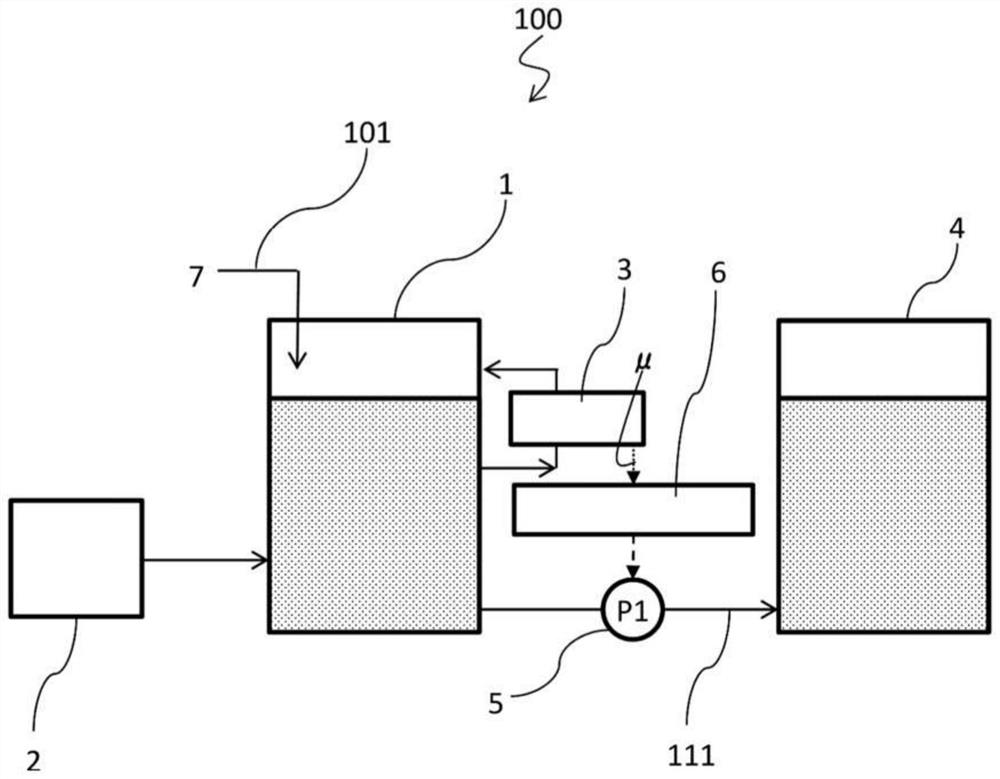
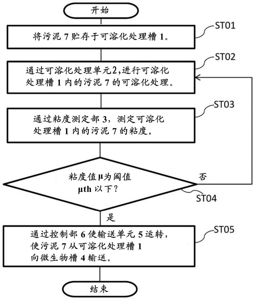
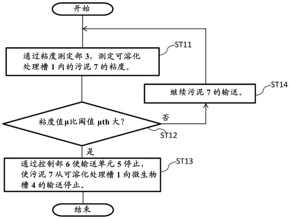
[0027] Below, based on Figure 1 to Figure 3 Embodiment 1 will be described. figure 1 It is a schematic diagram which shows the sludge treatment system in Embodiment 1. The sludge treatment system 100 includes: a solubilization treatment tank 1 that dissolves the sludge 7 inside, that is, a sludge solubilization unit; and a solubilization treatment unit that performs solubilization treatment on the sludge 7 in the solubilization treatment tank 1 2. Viscosity measurement unit 3 that measures the viscosity of sludge in the solubilization treatment tank 1 and outputs the measurement result as a viscosity value μ; microorganism tank 4 that contains microorganisms inside; transports from the solubilization treatment tank 1 to the microorganism tank 4 The conveying unit 5 of the sludge 7; the control part 6 which controls the conveying unit 5.
[0028] The solubilization treatment tank 1 is connected to a sludge pipe 101 , and the sludge 7 is sent into the solubilization treatmen...
Embodiment approach 2
[0057] Second, based on Figure 4 Embodiment 2 will be described. Figure 4 It is a schematic diagram which shows the sludge treatment system in Embodiment 2. In the figure, the same reference numerals are assigned to the same constituent devices and members as those of the sludge treatment system and the sludge treatment method in Embodiment 1, and description thereof will be omitted unless otherwise required. In addition, the sludge treatment system of Embodiment 2 treats the excess sludge produced|generated in the biological treatment tank. Here, the microorganism tank 4 of Embodiment 1 is used as a biological treatment tank. Since the configuration on the upstream side of the microorganism tank 4 is the same as that of the first embodiment, illustration and description thereof will be omitted. In addition, using the microorganism tank 4 as a biological treatment tank is an example, and it is not limited to this.
[0058] The sludge treatment system 200 is equipped with...
Embodiment approach 3
[0082] Second, based on Figure 5 Embodiment 3 will be described. Figure 5 It is a schematic diagram which shows the sludge treatment system in Embodiment 3. In the figure, the same reference numerals are attached to the same constituent devices and members as those of the sludge treatment system and sludge treatment method in Embodiments 1 and 2, and description thereof will be omitted unless otherwise required. In addition, in the sludge treatment system of Embodiment 3, the excess sludge generated in the biological treatment tank is solubilized with ozone gas, and returned to the biological treatment tank again.
[0083] The sludge treatment system 300 has: a solubilization treatment tank 1; a biological treatment tank 29 that processes waste water 27 to generate treated water 28 containing sludge; and transfers the treated water 28 containing sludge in the biological treatment tank 29 to a The sludge transfer unit 26 of the melting treatment tank 1; the ozone generator ...
PUM
 Abstract
Description
Claims
Application Information
 - R&D
- Intellectual Property
- Life Sciences
- Materials
- Tech Scout
- Unparalleled Data Quality
- Higher Quality Content
- 60% Fewer Hallucinations
Browse by: Latest US Patents, China's latest patents, Technical Efficacy Thesaurus, Application Domain, Technology Topic, Popular Technical Reports.
© 2025 PatSnap. All rights reserved.Legal|Privacy policy|Modern Slavery Act Transparency Statement|Sitemap|About US| Contact US: help@patsnap.com


