Epoxy floor troweling machine

An epoxy floor and trowel technology, applied in the direction of roads, buildings, building structures, etc., can solve the problems of different casting times, inability to adapt to the concrete surface, affecting the troweling effect of the floor, etc. , Increase the protective effect of wrapping, increase the effect of smoothing quality

Active Publication Date: 2021-06-08
SUZHOU BECKE ELECTRIC TECH CO LTD
View PDF4 Cites 0 Cited by
  • Summary
  • Abstract
  • Description
  • Claims
  • Application Information

AI Technical Summary

Problems solved by technology

[0006] In order to make up for the deficiencies of the existing technology, the power source drives the output shaft to rotate in the prior art, and then drives the smear to smooth the floor. However, due to the difference in the dryness and wetness of the floor, and the casting The time is different. When smoothing large-area floors, the same deflection angle cannot adapt to the concrete surface with different solidification degrees, which will affect the smoothing effect of the floor. An epoxy floor proposed by the present invention Trowel

Method used


Image

  • Epoxy floor troweling machine
  • Epoxy floor troweling machine
  • Epoxy floor troweling machine

Examples


Embodiment approach

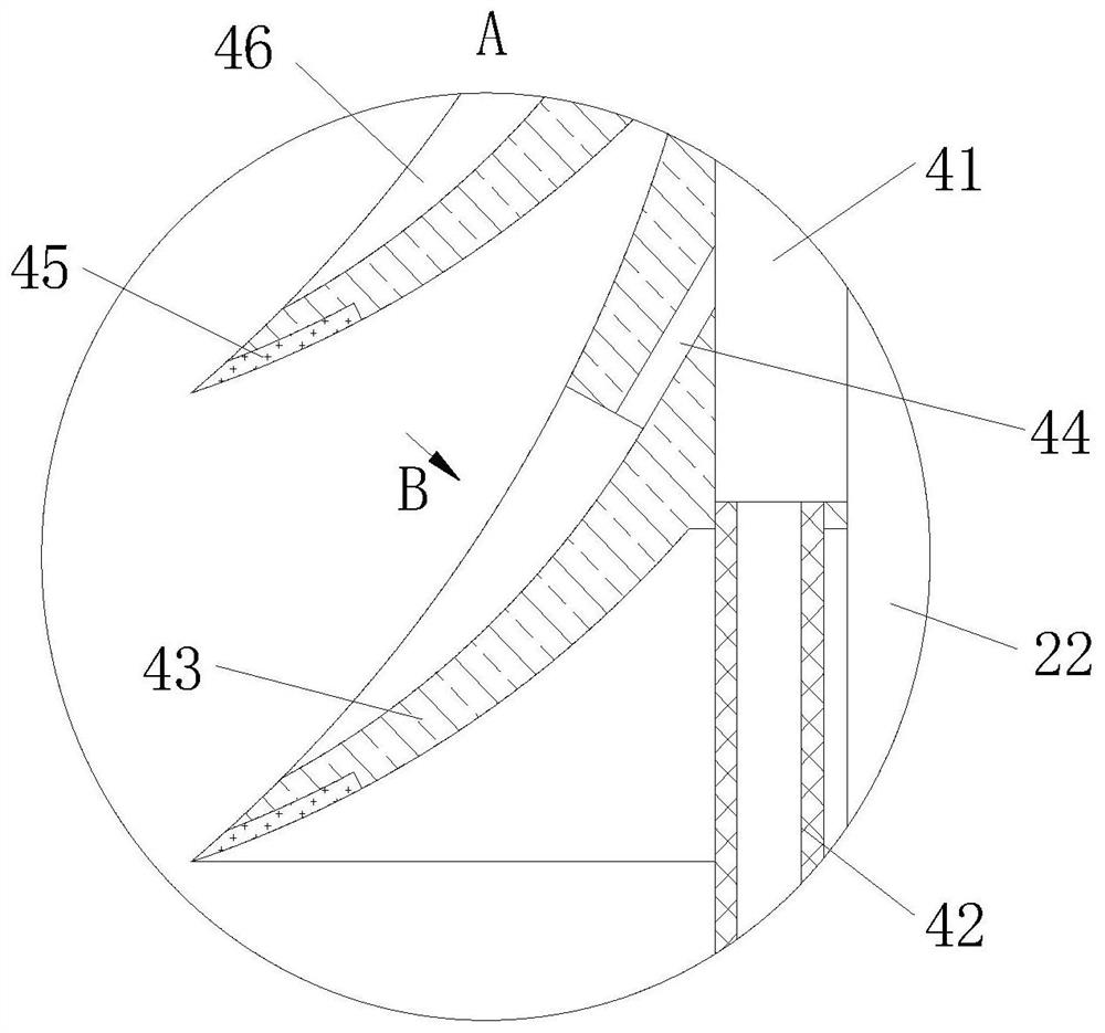
[0030] As an embodiment of the present invention, a group of elastic sawtooth tips 3 are evenly distributed on one side of the wave groove 25, and the ends of the sawtooth tips 3 are inclined in a direction away from the second hole 27; A sawtooth groove 31 is provided; the corrugated groove 25 and the corresponding position of the sawtooth groove 31 are fixedly connected with an arc-shaped magnetic piece 32, and the outer circumference of the sliding column 26 is the same as the magnetic pole on the side adjacent to the magnetic piece 32; the said sawtooth groove 31 is far away from the wave One side of the groove 25 is provided with an isosceles trapezoidal chute 33, and the two ends of the chute 33 communicate with the two ends of the wave groove 25; the side of the chute 33 near the second hole 27 is hinged with a shrapnel 35 by a pin 34, and the shrapnel The length of 35 is greater than the width of the chute 33, the free end of the shrapnel 35 is lapped on the edge of the...


PUM


Abstract

The invention belongs to the field of surface troweling and leveling instruments for concrete floors, pavements and the like, and particularly relates to an epoxy floor troweling machine. The epoxy floor troweling machine comprises a body, wherein a rotating seat is fixedly connected to the bottom of the body through an output shaft, a group of troweling plates are uniformly distributed on the periphery of the rotating seat, and the troweling plates are rotatably connected with the rotating seat through rotating shafts; elastic troweling pieces are fixedly connected to one side of each troweling plate, and rotating pins are fixedly connected to the sides, which are away from the troweling pieces, of the free ends of the troweling plates; and circular rings are fixedly connected to output shafts on the tops of the troweling pieces through brackets, air cylinders are arranged in the corresponding positions of the bottoms of the circular rings and the rotating pins, both ends of the air cylinders are respectively hinged to the circular rings and the rotating pins, and the air cylinders communicate with air pumps through pipelines and control valves. According to the epoxy floor troweling machine, the air cylinders are inflated through the air cylinders, so that the air cylinders extend and retract so as to control the angle of the troweling plates and the troweling pieces, the troweling pieces adapt to floors in different areas in real time, and the troweling quality of the troweling pieces to the floors is increased.

Description

technical field [0001] The invention belongs to the field of surface troweling and leveling equipment for concrete floors, road surfaces, etc., and specifically relates to an epoxy floor troweling machine. Background technique [0002] When constructing concrete pavements, floors, airport platforms, etc., it is necessary to tamp, compact, flatten and smooth the concrete surface to improve the compactness, wear resistance and surface finish of the concrete. In the past, mopping and mopping was mostly carried out manually, which was a great waste of human resources, and the quality was difficult to meet the standard. Most of the troweling machines on the market today are just a motor or a gasoline engine to drive a few pieces of smears or rollers to perform directional track smearing and leveling. Moreover, it is not easy to operate when the concrete moisture content is large, and it is easy to produce traces and redundant mortar. Therefore, it takes at least two or three tim...

Claims


Application Information

Patent Timeline
Patent Type & Authority Applications(China)
IPC IPC(8): E04F21/24
CPCE04F21/248E01C19/402E01C19/407
Inventor 顾浩
Owner SUZHOU BECKE ELECTRIC TECH CO LTD
Why Eureka
Try Eureka