Magnetic coupling type dry gas sealing structure
A technology of dry gas sealing and magnetic coupling, which is applied in the direction of engine sealing, engine components, mechanical equipment, etc., and can solve the problems of sealing interface friction and sealing, failure, etc.
- Summary
- Abstract
- Description
- Claims
- Application Information
AI Technical Summary
Problems solved by technology
Method used
Image
Examples
Embodiment 1
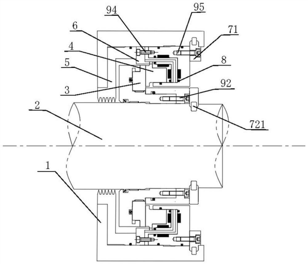
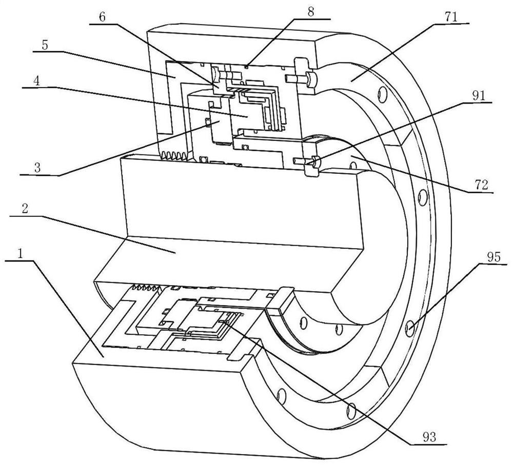
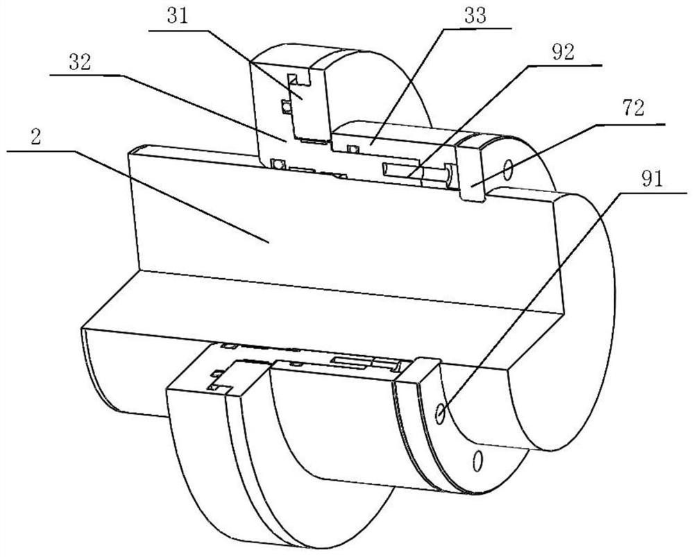
[0037] Such as figure 1 and figure 2 A magnetically coupled dry gas seal structure shown includes a housing 1, a rotor 2, a moving ring assembly 3 capable of rotating with the rotor 2, and a pushing and static assembly 4 matching the moving ring assembly 3. The moving ring assembly 3 includes a moving ring 31, and the static pushing assembly 4 includes a static ring seat 46, a static ring 41 located in the static ring seat 46, and several magnetic rings are arranged between the outer diameter of the static ring 41 and the inner diameter of the static ring seat 46. The first permanent magnet 431 that repels each other, the second permanent magnet 432 that several magnetic repulsions are arranged between the static ring seat 46 and the end of the static ring 41 away from the direction where the moving ring 31 is located in the axial direction; the first permanent magnet 431 is used to apply a radially inward thrust to the stationary ring 41 , and the second permanent magnet 43...
Embodiment 2
[0039] A magnetically coupled dry gas seal structure. On the basis of Embodiment 1, this embodiment includes a housing 1, a rotor 2, a moving ring assembly 3, a static and pushing assembly 4, comb teeth 5, an anti-rotation retaining ring 6, a split valve Snap rings, several O-rings and several locking screws; the moving ring assembly 3 is fixed on the bearing rotor 2 and rotates with the rotor 2, the pushing and static assembly 4 is fixed in the casing 1, and the anti-rotation The left side of the retaining ring 6 is in contact with the right side of the comb teeth 5 , the right side is in contact with the push static assembly 4 , the left side of the comb teeth 5 is in contact with the housing 1 , and the right side is in contact with the anti-rotation retaining ring 6 .
[0040] In one or more embodiments, the radial inner wall of the housing 1 is fixedly connected to the split snap ring I 71 , and the split snap ring I 71 is located on the axially outer end surface of the st...
PUM
 Abstract
Description
Claims
Application Information
 - R&D
- Intellectual Property
- Life Sciences
- Materials
- Tech Scout
- Unparalleled Data Quality
- Higher Quality Content
- 60% Fewer Hallucinations
Browse by: Latest US Patents, China's latest patents, Technical Efficacy Thesaurus, Application Domain, Technology Topic, Popular Technical Reports.
© 2025 PatSnap. All rights reserved.Legal|Privacy policy|Modern Slavery Act Transparency Statement|Sitemap|About US| Contact US: help@patsnap.com


