A magnetically coupled dry gas seal structure

A technology of dry gas sealing and magnetic coupling, applied in the direction of engine sealing, mechanical equipment, engine components, etc., can solve problems such as failure, sealing interface friction and sealing, and achieve the effect of improving reliability

Active Publication Date: 2021-12-21
LANZHOU UNIVERSITY OF TECHNOLOGY
View PDF3 Cites 1 Cited by
  • Summary
  • Abstract
  • Description
  • Claims
  • Application Information

AI Technical Summary

Problems solved by technology

[0004] The purpose of the present invention is to provide a magnetic coupling type dry gas seal structure to solve the sealing interface friction and sealing of the large shaft diameter dry gas seal device in the prior art under the "three high" working conditions of high pressure, high temperature and high speed. In order to achieve the purpose of making the dry gas sealing device applicable to the field of large shaft diameter machinery and improving the sealing reliability

Method used


Image

  • A magnetically coupled dry gas seal structure
  • A magnetically coupled dry gas seal structure
  • A magnetically coupled dry gas seal structure

Examples


Embodiment 1

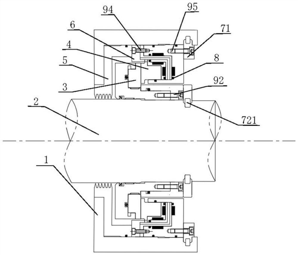
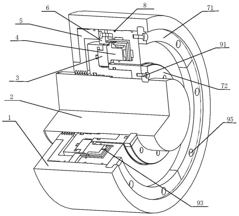
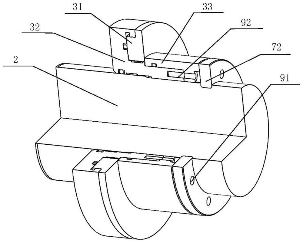
[0037] Such as figure 1 and figure 2 A magnetically coupled dry gas seal structure shown includes a housing 1, a rotor 2, a moving ring assembly 3 capable of rotating with the rotor 2, and a pushing and static assembly 4 matching the moving ring assembly 3. The moving ring assembly 3 includes a moving ring 31, and the static pushing assembly 4 includes a static ring seat 46, a static ring 41 located in the static ring seat 46, and several magnetic rings are arranged between the outer diameter of the static ring 41 and the inner diameter of the static ring seat 46. The first permanent magnet 431 that repels each other, the second permanent magnet 432 that several magnetic repulsions are arranged between the static ring seat 46 and the end of the static ring 41 away from the direction where the moving ring 31 is located in the axial direction; the first permanent magnet 431 is used to apply a radially inward thrust to the stationary ring 41 , and the second permanent magnet 43...

Embodiment 2

[0039] A magnetically coupled dry gas seal structure. On the basis of Embodiment 1, this embodiment includes a housing 1, a rotor 2, a moving ring assembly 3, a static and pushing assembly 4, comb teeth 5, an anti-rotation retaining ring 6, a split valve Snap rings, several O-rings and several locking screws; the moving ring assembly 3 is fixed on the bearing rotor 2 and rotates with the rotor 2, the pushing and static assembly 4 is fixed in the casing 1, and the anti-rotation The left side of the retaining ring 6 is in contact with the right side of the comb teeth 5 , the right side is in contact with the push static assembly 4 , the left side of the comb teeth 5 is in contact with the housing 1 , and the right side is in contact with the anti-rotation retaining ring 6 .

[0040] In one or more embodiments, the radial inner wall of the housing 1 is fixedly connected to the split snap ring I 71 , and the split snap ring I 71 is located on the axially outer end surface of the st...


PUM


Abstract

The invention discloses a magnetic coupling type dry gas sealing structure, which comprises a casing, a rotor, a moving ring assembly capable of rotating with the rotor, and a pushing and static assembly matched with the moving ring assembly, and the moving ring assembly includes a moving ring assembly ring, the static pushing assembly includes a static ring seat, a static ring located in the static ring seat, a number of first permanent magnets magnetically repelling each other are arranged between the outer diameter of the static ring and the inner diameter of the static ring seat, and the static ring is positioned along the A number of second permanent magnets magnetically repelling each other are arranged between one end of the direction away from the moving ring and the seat of the static ring; the first permanent magnet is used to apply a radially inward thrust to the static ring, and the second permanent magnet Magnets are used to apply an axial inward thrust to the stationary ring. The invention is used to solve the problems of the seal interface friction and seal failure of the large shaft diameter dry gas seal device in the prior art under the three high working conditions of high pressure, high temperature and high speed, and realize that the dry gas seal device can be applied to the large shaft In the field of diameter machinery, the purpose of improving sealing reliability.

Description

technical field [0001] The invention relates to the field of dry gas sealing, in particular to a magnetic coupling type dry gas sealing structure. Background technique [0002] Dry gas sealing is a non-contact mechanical sealing technology, because the opening force formed by the increase of the end membrane pressure is greater than the closing force acting on the sealing ring, and a thin layer of gas film is formed between the friction pairs, so The formed air film completely blocks the relatively low-pressure sealing medium leakage channel, which is a technology to achieve zero leakage or zero escape of the sealing medium. [0003] However, in the prior art, the application of dry gas seals in high-pressure, high-temperature, high-speed large-shaft diameter turbomachinery (expanders, compressors, gas turbines, etc.) has been limited, mainly due to the following reasons: first, Under the condition of high service ambient temperature, the spring on the back of the tradition...

Claims


Application Information

Patent Timeline
Patent Type & Authority Patents(China)
IPC IPC(8): F16J15/43
CPCF16J15/43
Inventor 严如奇杨小成陈汉卿徐洁丁俊华王世鹏张伟政丁雪兴
Owner LANZHOU UNIVERSITY OF TECHNOLOGY
Why Eureka
Try Eureka