Method for detecting leakage of water supply network
A technology for water supply pipeline network and underground water supply pipeline, which can be used in pipeline systems, mechanical equipment, gas/liquid distribution and storage, etc., and can solve the problems of complexity, high installation and use costs
- Summary
- Abstract
- Description
- Claims
- Application Information
AI Technical Summary
Problems solved by technology
Method used
Image

Examples
Embodiment Construction
[0025] In order to make the purpose, features and advantages of the present invention more obvious and understandable, the technical solutions in the embodiments of the present invention will be clearly and completely described below in conjunction with the accompanying drawings in the embodiments of the present invention. Obviously, the described The embodiments are only some of the embodiments of the present invention, but not all of them. Based on the embodiments of the present invention, all other embodiments obtained by those skilled in the art without making creative efforts belong to the protection scope of the present invention.
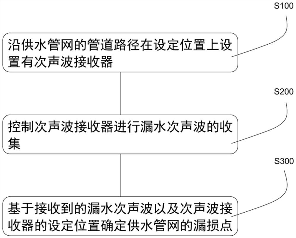
[0026] see figure 1 , the embodiment of the present invention provides a method for detecting leakage of a water supply pipe network, comprising the following steps:
[0027] Step S100: setting an infrasonic receiver at a set position along the pipeline path of the water supply network;
[0028] Step S200: controlling the infrasonic wave re...
PUM
 Abstract
Description
Claims
Application Information
 - R&D
- Intellectual Property
- Life Sciences
- Materials
- Tech Scout
- Unparalleled Data Quality
- Higher Quality Content
- 60% Fewer Hallucinations
Browse by: Latest US Patents, China's latest patents, Technical Efficacy Thesaurus, Application Domain, Technology Topic, Popular Technical Reports.
© 2025 PatSnap. All rights reserved.Legal|Privacy policy|Modern Slavery Act Transparency Statement|Sitemap|About US| Contact US: help@patsnap.com