
A Visual Modeling Method for Virtual Operating Environment of Complex Embedded Systems

An embedded system and operating environment technology, applied in the input/output process of data processing, instruments, geometric CAD, etc., can solve the problems of complex modeling process, difficult description of system composition relationship, poor reusability, etc., to simplify the construction process , the effect of improving R&D efficiency and test adequacy

Active Publication Date: 2022-06-24
BEIJING INST OF COMP TECH & APPL
View PDF0 Cites 0 Cited by
  • Summary
  • Abstract
  • Description
  • Claims
  • Application Information

AI Technical Summary

Problems solved by technology

[0006] The purpose of the present invention is to provide a visual modeling method for the virtual operating environment of complex embedded systems, which is used to solve the complex modeling process of the virtual operating environment of complex embedded systems in the prior art, the difficulty in describing the system composition relationship, the high cost of model development, The problem of poor reusability

Method used


Image

  • A Visual Modeling Method for Virtual Operating Environment of Complex Embedded Systems
  • A Visual Modeling Method for Virtual Operating Environment of Complex Embedded Systems
  • A Visual Modeling Method for Virtual Operating Environment of Complex Embedded Systems

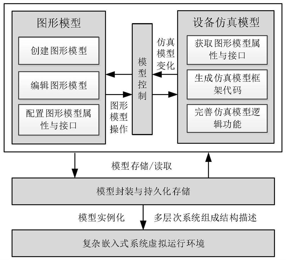
Examples


Embodiment Construction

[0021] In order to make the purpose, content, and advantages of the present invention clearer, the specific embodiments of the present invention will be described in further detail below with reference to the accompanying drawings and embodiments.

[0022] A visual modeling method of a complex embedded system virtual operating environment of the present invention includes:

[0023] The first step is to build a graphical model of the entity object

[0024] The visual modeling technology of the virtual operating environment uses the graphic editing framework to carry out multi-level model description and design, realize the creation and editing of graphical models, and generate graphical models of physical objects such as processors, external devices, excitation devices, and buses. Interfaces and properties that correspond to real physical device capabilities.

[0025] The second step, configure the graphical model interface and properties

[0026] Configure graphical model in...


PUM


Abstract

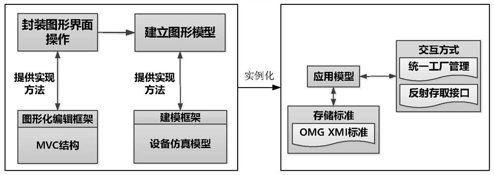
The present invention relates to a visual modeling method for a virtual operating environment of a complex embedded system, which includes: the first step, constructing a graphical model of an entity object; the second step, configuring the graphical model interface and attributes; the third step, generating The equipment simulation model includes: converting the interfaces and attributes described by the graphical model into corresponding interface functions and attribute variables, automatically generating the framework code of the equipment simulation model, and developing the logical function of the equipment simulation model based on this framework; the fourth step , Encapsulate the equipment simulation model and store it persistently, including: encapsulating the operation of the graphical interface, and establishing a bidirectional mapping between the equipment simulation model and the graphical model; System configuration files. The invention can effectively simplify the construction process of the virtual operating environment of the complex embedded system, and further improve the efficiency of embedded software research and development and the adequacy of testing.

Description

technical field [0001] The invention relates to an embedded system development technology, in particular to a visualization modeling method for a virtual operating environment of a complex embedded system. Background technique [0002] In the process of developing an embedded system, the development and debugging of embedded software is generally carried out through the real target machine operating environment. The target machine operating environment includes processors, peripheral devices, connection buses, and supporting excitation devices, etc., but it is limited by the embedded system hardware. Due to the characteristics of limited resources and strong hardware interface specificity, it is difficult to accurately count the dynamic execution of embedded software, and it is difficult to guarantee the development efficiency and testing adequacy of embedded software. Therefore, a virtual operating environment modeling method is often used to model and simulate complex embe...

Claims


Application Information

Patent Timeline
Patent Type & Authority Patents(China)
IPC IPC(8): G06F30/12G06F3/04845G06F111/20
CPCG06F30/12G06F3/04845G06F2111/20
Inventor 付修锋孔祥炳安恒金玉川贾张涛李雅斯
Owner BEIJING INST OF COMP TECH & APPL
Learn More