Design method of multipath radial power distributor/synthesizer
A design method and technology of synthesizers, applied in circuits, waveguide-type devices, electrical components, etc., can solve problems such as long simulation optimization time, difficulty in adding design and optimization, difficulty in power distribution/synthesis, etc., to save design and optimization. time, reducing the effect of optimized parameters
- Summary
- Abstract
- Description
- Claims
- Application Information
AI Technical Summary
Problems solved by technology
Method used
Image
Examples
Embodiment 1
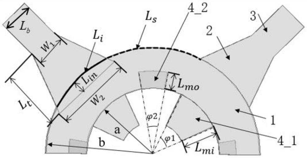
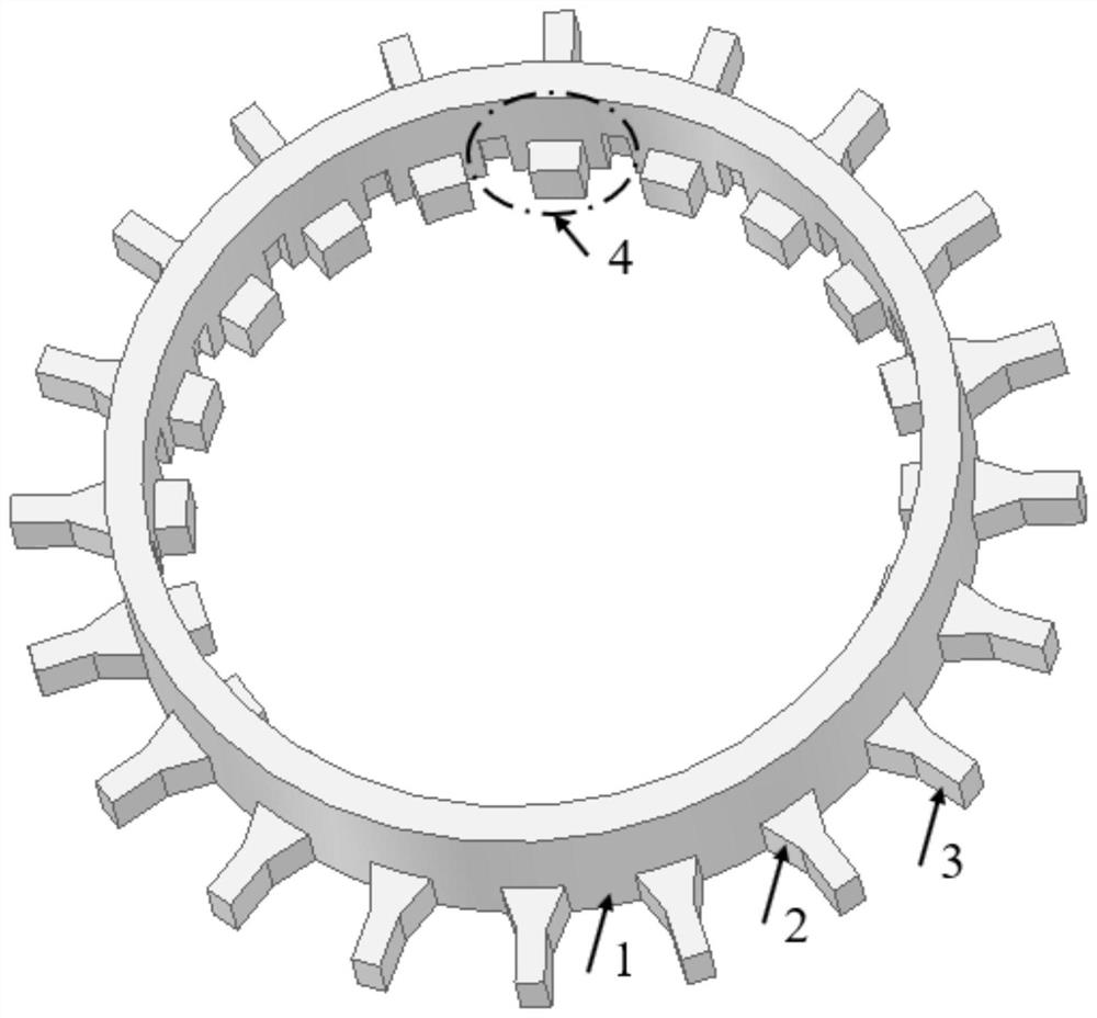
[0026] Set N=20, calculate according to step 1 to obtain the outer radius of the coaxial waveguide (1) b=51.46mm; according to step 2, take b-a=0.55λ=4.7mm, calculate and obtain the inner radius of the coaxial waveguide (1) a=46.76mm ;According to step 3, the size of the matching structure is calculated as follows: the fan-shaped slot (4_1) corresponds to the central angle ThicknessL mi =4mm, the fan-shaped block (4_2) corresponds to the central angle L mo =0.5L mi = 2mm; the model of the standard rectangular waveguide selected according to step 4 is BJ320 (7.112mm × 3.556mm); according to step 5, the size of the straight trapezoidal transition waveguide structure (2) is: W 1 =3.556mm, W 2 =8.65mm, L t =7mm, L in = 1.5mm; Simulation modeling is carried out according to the device structure size calculated by the above steps, and the structure diagram is as follows figure 2 As shown, the lengths of the standard rectangular waveguide and the coaxial waveguide are both ...
Embodiment 2
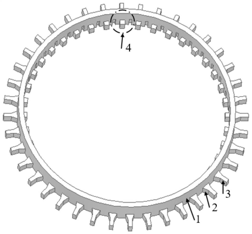
[0028] N=40 is set, and all the other steps are the same as in Embodiment 1. The dimensions of the device calculated through the design steps are respectively: b=99.57mm, a=94.87mm, L mo =0.5L mi = 2mm, W 1 =3.556mm, W 2 =8.65mm, L t =7mm, L in =1.5mm, the standard rectangular waveguide is BJ320 (7.112mm×3.556mm), and the waveguide length is 20mm. Through simulation modeling, it is obtained as image 3 In the structure shown, the lengths of the standard rectangular waveguide and the coaxial waveguide are both 20mm. The S-parameters of this structure are calculated by simulation as Figure 5As shown, the insertion loss of the device at 35GHz is 0.11dB, and the insertion loss in the 34.51GHz-35.68GHz frequency band is less than 0.2dB.
PUM
 Abstract
Description
Claims
Application Information
 - R&D
- Intellectual Property
- Life Sciences
- Materials
- Tech Scout
- Unparalleled Data Quality
- Higher Quality Content
- 60% Fewer Hallucinations
Browse by: Latest US Patents, China's latest patents, Technical Efficacy Thesaurus, Application Domain, Technology Topic, Popular Technical Reports.
© 2025 PatSnap. All rights reserved.Legal|Privacy policy|Modern Slavery Act Transparency Statement|Sitemap|About US| Contact US: help@patsnap.com


