
Active damping control system and method

A control system and damping technology, applied to AC network circuits, electrical components, and AC networks to reduce harmonics/ripples, etc., can solve problems such as low quality of incoming current, amplifying high-frequency noise, and affecting damping effects

Pending Publication Date: 2021-06-08
STATE GRID CORP OF CHINA +2
View PDF0 Cites 0 Cited by
  • Summary
  • Abstract
  • Description
  • Claims
  • Application Information

AI Technical Summary

Problems solved by technology

[0005] The purpose of the present invention is to provide a control system and method of active damping to solve the problem of conventional differential and its equivalent implementation method, amplifying high-frequency noise, causing low quality of incoming current and affecting the damping effect

Method used


Image

  • Active damping control system and method
  • Active damping control system and method
  • Active damping control system and method

Examples


Embodiment 1

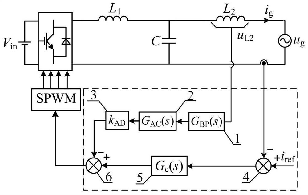
[0042] by figure 1 The single-phase LCL type grid-connected inverter shown in the example is an active damping control system, which involves the current main control loop of the LCL type inverter and the band-pass filter + lead correction link to feed back the grid-side inductance voltage active The control system composed of the damping branch includes a bandpass filter module 1 , a lead correction link 2 , a damping branch feedback coefficient module 3 , a first subtractor module 4 , a current controller module 5 and a second subtractor module 6 .

[0043] Based on above-mentioned a kind of active damping method, described method comprises the following steps:

[0044] S1: The measured grid-side inductance voltage is firstly processed by the band-pass filter module 1;

[0045] S2: After the grid-side inductance voltage passes through the band-pass filter module 1, it continues to be corrected through the advanced correction link 2;

[0046] S3: After the grid-side inducta...

Embodiment 2

[0079] The present invention can be applied to differential feedback filter capacitor voltage active damping, and also relates to a control system composed of LCL type inverter current main control loop and band-pass filter + lead correction link 2 feedback capacitor voltage active damping branch, including Band-pass filter module 1 , lead correction link 2 , damping branch feedback coefficient module 3 , first subtractor module 4 , current controller module 5 and second subtractor module 6 .

[0080] The specific steps are:

[0081] Based on the above-mentioned active damping method, the active damping steps applied to the filter capacitor voltage feedback are as follows:

[0082] S1: The measured filter capacitor voltage is first processed by the band-pass filter module 1;

[0083] S2: After the filter capacitor voltage passes through the bandpass filter module 1, it continues to be corrected through the advanced correction link 2;

[0084] S3: The filter capacitor voltage...


PUM


Abstract

The invention discloses an active damping control system and method, and relates to a control system composed of an LCL type grid-connected inverter main control loop and a band-pass filter+lead correction link active damping branch. The method comprises the following steps: firstly, a sampled grid-side inductive voltage passes through a band-pass filter module, a lead correction link module and a damping branch coefficient module to generate a first output signal; meanwhile, the network access current and the given reference current are subtracted through a subtracter, and an obtained current deviation signal passes through a current controller to generate a second output signal; and the first output signal and the second output signal are subtracted by a subtracter to obtain a modulated wave, and the modulated wave is input to a PWM module to generate a driving signal to drive an inverter power device. Compared with other differential active damping methods, the band-pass filter and lead correction link feedback grid-side inductive voltage active damping method provided by the invention can better inhibit the influence of high-frequency noise and power grid background harmonic waves on the quality of current entering the grid.

Description

technical field [0001] The invention relates to the related technical field of grid-connected inverter control, in particular to an active damping control system and method. Background technique [0002] Under the premise of achieving the same filtering effect, the LCL filter has the advantages of small size and low cost compared with the single L filter, but it is prone to resonance and cause grid-connected system instability. Common methods to suppress LCL filter resonance can be divided into passive damping and active damping. Among them, passive damping is simple to implement and not limited by switching frequency, but increases system loss. [0003] Active damping is realized by feeding back the state quantity of the LCL filter, which has the advantages of simple implementation, flexible control and strong robustness. Among the existing methods, the filter capacitor current proportional feedback active damping has been widely used because of the simplicity of the algor...

Claims


Application Information

Patent Timeline
IPC IPC(8): H02J3/01H02J3/38H02J3/24
CPCH02J3/01H02J3/38H02J3/241Y02E40/40
Inventor 王爱华葛维春李铁崔岱高凯陈晓东罗桓桓姜枫唐俊刺王明凯李欣蔚李明明肖华锋
Owner STATE GRID CORP OF CHINA
Learn More