Lifting table frame

A table frame and lifting column technology, which is applied in the field of lifting tables, can solve the problems of easy shaking and unstable lifting process of the lifting table, and achieve the effect of simple structure and stable operation process.

Inactive Publication Date: 2021-06-11
江苏慕林智造科技股份有限公司
View PDF5 Cites 2 Cited by
  • Summary
  • Abstract
  • Description
  • Claims
  • Application Information

AI Technical Summary

Problems solved by technology

The lifting process of the existing lifti

Method used


Image

  • Lifting table frame
  • Lifting table frame
  • Lifting table frame

Examples


Embodiment

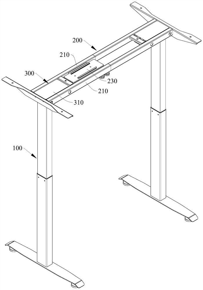
[0035] Such as figure 1 As shown, the present embodiment provides a lifting table frame, including: lifting column 100; desktop installation frame 200, fixed on the upper end of lifting column 100; Box 200 lifts.

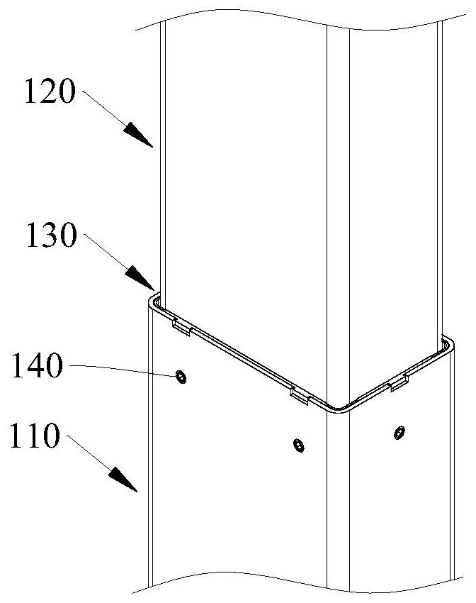
[0036] Such as figure 2 , Figure 4 , Figure 7 , Figure 10 and Figure 11 As shown, in this embodiment, the lifting column 100 includes: an inner tube 120; and an outer tube 110 sleeved outside the inner tube 120; Between the inner tubes 120; the sliding piece 150 is installed on the outer wall of the lower end of the inner tube 120; wherein the driving mechanism 300 drives the inner tube 120 to rise and fall.

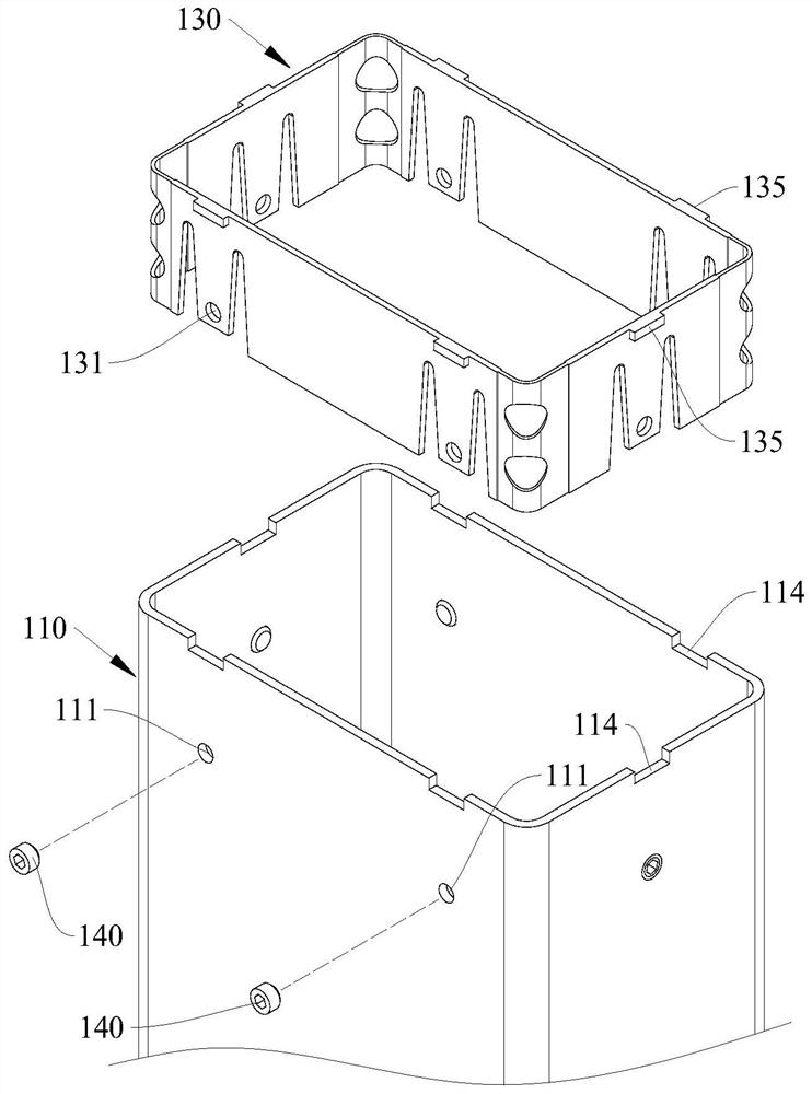
[0037] In this embodiment, the upper end of the outer tube 110 is provided with a slider 130, which can avoid direct contact between the inner and outer tube walls, fill the gap between the inner and outer tube walls, and improve the smoothness and stability of operation; At the same time, it can eliminate the noise and jam caused by the direct con...

Embodiment approach

[0065] Such as Figure 12 As shown, as an optional implementation of the driving mechanism 300 of this embodiment, the driving mechanism 300 includes: a driving box 310 fixed on the upper end of the inner tube 120, with a driver inside; a screw rod 320 pierced inside Inside the tube 120; the screw sleeve 330 is set in the outer tube 110, its bottom end is fixedly connected with the outer tube 110, and the top end is fixed with a screw nut 340 sleeved on the screw rod 320; wherein the driver drives the screw rod 320 rotates to drive the inner tube 120 up and down in cooperation with the screw nut 340.

[0066] In this embodiment, the structure of the driving mechanism 300 is simple, and the bottom end of the screw sleeve 330 can be fixedly connected to the outer tube 110 directly, or can be fixedly connected to the outer tube 110 through the support seat of the table leg; the inner tube 120 The upper end of the can be fixedly connected with the drive box 310; the driver can be...


PUM


Abstract

The invention belongs to the technical field of lifting tables and particularly relates to a lifting table frame. The lifting table frame comprises a lifting stand column; a desktop mounting frame fixed at an upper end of the lifting stand column; a driving mechanism used for driving the lifting stand column to ascend and descend so as to drive the tabletop mounting frame to ascend and descend. When the sliding block in the lifting table frame is installed, the sliding block can be arranged on the inner pipe in a sleeving mode and then is directly inserted into the outer pipe, an avoiding notch does not need to be formed in the inner pipe, and machining cost of the inner pipe is reduced; components such as the sliding block, the driving box and the control box are mostly connected in an inserting and clamping mode, assembling is easy, convenient and rapid, the modularization degree is high, and use of fixing pieces is reduced; the mounting strength of the sliding block on the outer pipe is high, stability is good, the service life can be prolonged, disassembly and assembly are simple and convenient, and parts in the pipe are convenient to overhaul and replace; the sliding piece and the sliding block act together, and overall stability of the lifting stand column in the operation process can be improved.

Description

technical field [0001] The invention belongs to the technical field of lift tables, and in particular relates to a lift table frame. Background technique [0002] Desks are indispensable for daily life and office supplies. The height of traditional desks is fixed and cannot be adjusted according to the user's personal situation and actual needs. In terms of diseases, the height-adjustable lifting table can be adjusted according to the user's different body heights to improve comfort and relieve pain. [0003] There are many different types of desks available, including single-column desks and multi-column desks. The lifting process of the existing lifting table is unstable and prone to shaking. Contents of the invention [0004] The object of the present invention is to provide a lifting table frame. [0005] In order to solve the above technical problems, the present invention provides a lifting table frame, comprising: a lifting column; a desktop mounting frame fixed ...

Claims


Application Information

Patent Timeline
IPC IPC(8): A47B9/04A47B13/02
CPCA47B9/04A47B13/02
Inventor 曾少卿刘翻霞
Owner 江苏慕林智造科技股份有限公司
Why Eureka
Try Eureka