Check patentability & draft patents in minutes with Patsnap Eureka AI!

Dry sludge crushing device

A crushing device and dry sludge technology, which is applied in the direction of grain processing, etc., can solve the problems of easy blockage of the output and poor feeding, and achieve the effects of rapid output, increased service life, and simple and reliable device process

Pending Publication Date: 2021-06-11
浙江物华天宝能源环保有限公司
View PDF0 Cites 0 Cited by
  • Summary
  • Abstract
  • Description
  • Claims
  • Application Information

AI Technical Summary

Problems solved by technology

[0006] The embodiment of the present invention provides a dry sludge crushing device to solve the problems in the related art that the feed of the sludge crusher is not smooth and the discharge is easy to be blocked.

Method used


Image

  • Dry sludge crushing device

Examples


Embodiment Construction

[0021] It should be noted that, in the case of no conflict, the embodiments in the present application and the features in the embodiments can be combined with each other. The present invention will be described in detail below with reference to the accompanying drawings and examples.

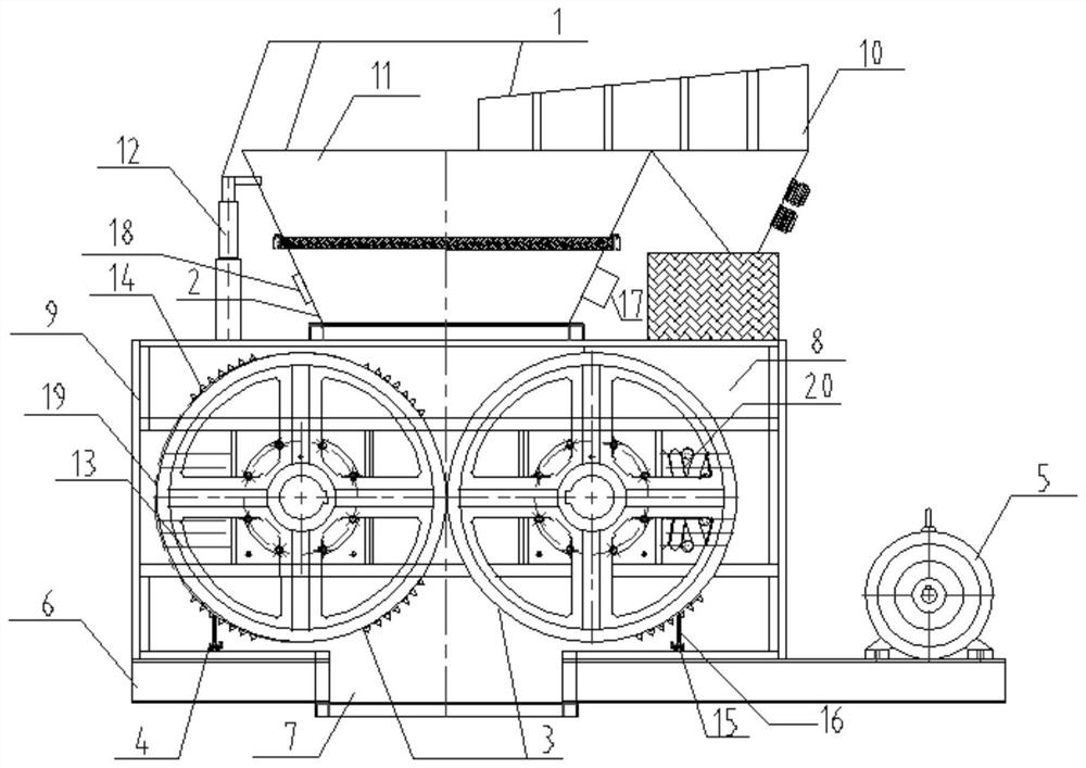
[0022] Such as figure 1 As shown, the embodiment of the present invention provides a dry sludge crushing device, which includes a housing 9, a feeding unit 1, a feeding unit 2, a crushing unit 3, a plugging removal unit 4, and a discharge unit 7. The feed unit 1 supplies dry sludge to the feed unit 2, the feed unit 2 is installed on the upper end of the housing 9, and the feed unit 2 transfers the dry sludge to the The crushing unit 3, the crushing unit 3 and the blockage removal unit 4 are located in the housing 9, the crushing unit 3 crushes the dry sludge, and the blockage removal unit is arranged below the crushing unit 3 4. The discharge unit 7 is arranged on the bottom of the housing 9,...


PUM


Abstract

The invention discloses a dry sludge crushing device. The dry sludge crushing device is characterized by comprising a shell, a supplying unit, a feeding unit, a crushing unit, a blockage clearing unit and a discharging unit, wherein the supplying unit supplies dry sludge to the feeding unit; the feeding unit is installed at the upper end of the shell; the feeding unit transfers the dry sludge to the crushing unit arranged below the feeding unit; the crushing unit and the blockage clearing unit are located in the shell; the crushing unit crushes the dry sludge; the blockage clearing unit is arranged below the crushing unit; the discharging unit is arranged at the bottom end of the shell; and the crushed dry sludge is discharged from the discharging unit. According to the dry sludge crushing device, by integrating the feeding unit, the crushing unit, the blockage clearing unit and the like, the remarkable problems that a crusher is unsmooth in feeding and prone to blockage during discharging are solved, and high efficiency, environment friendliness, energy conservation and safety in the sludge crushing process are achieved.

Description

technical field [0001] The invention belongs to the field of environmental protection equipment, and in particular relates to a dry sludge crushing device. Background technique [0002] In the conventional sludge incineration process, the sludge is directly poured into the silo, and then sent to the incinerator through the conveying equipment. The sludge formed in large pieces is often blocked, which makes the transportation efficiency low, so it is often required to be coarsely crushed. The crusher is directly connected to the bottom of the silo, which may easily cause excessive load fluctuations. In order to prevent the crusher from being overloaded and stop running, it is necessary to balance the feeding speed; adding a conveyor between the silo and the crusher to achieve uniform feeding has the disadvantages of large equipment footprint and high energy consumption. [0003] Secondly, when the sludge is fed, the hardness is different, and the crushing effect is uneven. ...

Claims


Application Information

Patent Timeline
IPC IPC(8): B02C4/08B02C4/28B02C4/30B02C4/40B02C4/42B02C4/32B02C23/04B02C23/02B02C25/00
CPCB02C4/08B02C4/28B02C4/286B02C4/30B02C4/32B02C4/40B02C4/42B02C23/02B02C23/04B02C25/00B02C2201/06
Inventor 余晓琴沈振彬林振国汪盼盼欧阳璐钟婷姗金余其
Owner 浙江物华天宝能源环保有限公司
Features
  • R&D
  • Intellectual Property
  • Life Sciences
  • Materials
  • Tech Scout
  • Unparalleled Data Quality
  • Higher Quality Content
  • 60% Fewer Hallucinations
Learn More