
Differential long core head pipe drawing method

A technology of pipe drawing and core head, applied in metal drawing forming tools, metal wire drawing, metal processing equipment, etc., can solve the problem of easily scratched inner surface, cumbersome drawing process of moving long mandrel, and limitation of process pipe specifications. and other problems to achieve the effect of solving surface scratches, reducing the pulling force and improving work efficiency

Pending Publication Date: 2021-06-11
INST OF METAL RESEARCH - CHINESE ACAD OF SCI
View PDF5 Cites 0 Cited by
  • Summary
  • Abstract
  • Description
  • Claims
  • Application Information

AI Technical Summary

Problems solved by technology

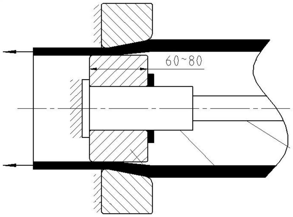
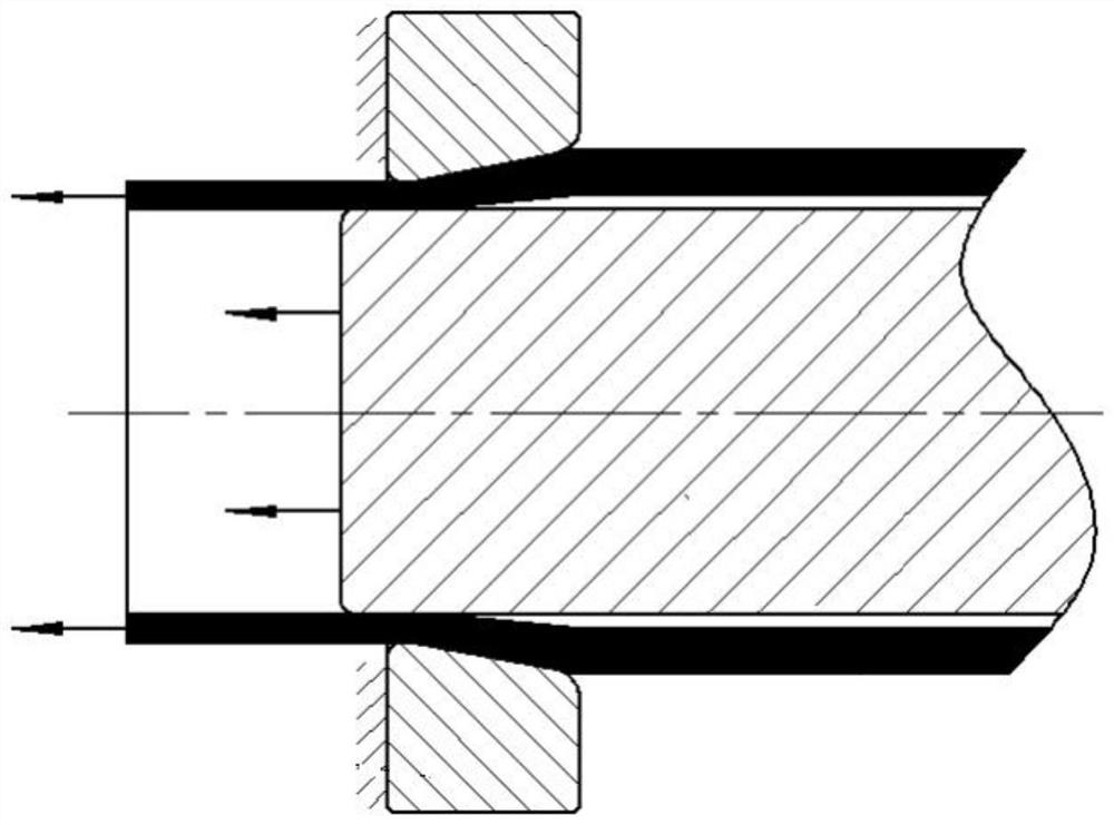
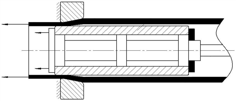
[0006] The purpose of the present invention is to provide a differential long mandrel pipe drawing method, which solves the problems that the inner surface of the pipe is easily scratched when drawing the fixed short mandrel, and the drawing process of the moving long mandrel is too cumbersome and the process is limited by the specification of the pipe.

Method used


Image

  • Differential long core head pipe drawing method
  • Differential long core head pipe drawing method
  • Differential long core head pipe drawing method

Examples


Embodiment 1

[0021] 1) The material is 2024 aluminum alloy, the diameter is φ180mm, the wall thickness is 10mm, and the length is 3m. It needs to be drawn with a core to form a pipe with a diameter of φ176mm, a wall thickness of 8.5mm, and a length of 3.46m;

[0022] 2) First make the drawing head, and perform local diameter reduction processing on the pipe head to form a diameter reduction section with a diameter of φ174mm and a length of about 100mm;

[0023] 3) Choose a long core head with a working belt length of 450mm and a diameter of φ159mm to install on the core head seat, the core head seat is installed on the core head pull rod, and the core head is fixed with a lock nut so that it is integrated with the pull rod;

[0024] 4) Install the φ176mm outer mold into the mold base;

[0025] 5) Lubricate the working cone of the outer mold and the core head, the working belt and the inner and outer surfaces of the pipe, requiring uniform lubrication and moderate thickness of the oil film;...

Embodiment 2

[0032] The drawing process is the same as in Example 1, except that the material is 7475 aluminum alloy, the diameter is φ30mm, the wall thickness is 1.5mm, and the length is 8m. 1.3mm, length of 10m pipe.

[0033] Use a long core head with a diameter of φ24.9mm and a working belt length of 3.3m, and the moving speed ratio of the pipe and the long core head is 3:1.

[0034] After drawing, the inner and outer surfaces of the pipe are smooth, without scratches, and the size meets the requirements.

Embodiment 3

[0036] The drawing process is the same as in Example 1, except that the material is 316 stainless steel, the diameter is φ70mm, the wall thickness is 5mm, and the length is 5m. 6m pipe.

[0037] Use a long core head with a diameter of φ58.6mm and a working belt length of 3m, and the moving speed ratio of the pipe and the long core head is 2:1.

[0038] After drawing, the inner and outer surfaces of the pipe are smooth, without scratches, and the size meets the requirements.


PUM

PropertyMeasurementUnit
diameteraaaaaaaaaa
thicknessaaaaaaaaaa
diameteraaaaaaaaaa

Abstract

The invention belongs to the technical field of metal processing, aims to provide a differential long core head pipe drawing method, and solves the problems that the inner surface of a pipe is easily scratched during fixed short core head drawing, the drawing process of a movable long core rod is too tedious, and the process is limited by the specification of the pipe. According to the method, the pipe and the core head move in the same direction at a certain speed ratio in the drawing process, the pipe and the core head are separated after drawing is finished, the length of a working tape of the core head is greatly increased, an additional core removing procedure is not needed, and the drawing efficiency is improved while the drawing quality of the pipe is guaranteed. The method can be used for drawing the belt core of a metal pipe with certain plasticity, is particularly suitable for processing small-diameter, thin-wall and long pipes made of aluminum alloy and austenitic stainless steel materials, and can effectively avoid drawing damage of the pipes.

Description

technical field [0001] The invention belongs to the technical field of metal processing, and in particular provides a method for drawing a pipe with a differential long core head. Background technique [0002] Pipe core drawing refers to the plastic deformation method in which the drawing trolley drives the pipe through the annular area formed by the outer mold and the core head to achieve diameter reduction and wall reduction. [0003] There are two main methods of cored drawing for pipes: fixed short core head drawing and moving long mandrel drawing. The working belt length of the fixed short core head drawing method is generally 3-8mm. Due to the short working belt, for the drawing of thin-walled and long pipes, the fixed short core head method can easily cause scratches on the inner surface; the moving long core head The length of the working belt of the mandrel in the rod drawing method is the length of the pipe, and the surface of the pipe is not easily scratched, but...

Claims


Application Information

Patent Timeline
Patent Type & Authority Applications(China)
IPC IPC(8): B21C1/00B21C3/00
CPCB21C1/00B21C3/00
Inventor 刘振伟张振
Owner INST OF METAL RESEARCH - CHINESE ACAD OF SCI
Learn More