Wind power blade lightning arrester mounting device and mounting method

A technology for wind power blades and installation devices, which is applied in the field of installation devices for wind power blade lightning receptors. It can solve problems such as inability to accurately drill holes vertically to the base, and achieve the effects of avoiding electric field distortion and preventing water accumulation

Pending Publication Date: 2021-06-11
JILIN CHONGTONG CHENGFEI NEW MATERIAL
View PDF0 Cites 2 Cited by
  • Summary
  • Abstract
  • Description
  • Claims
  • Application Information

AI Technical Summary

Problems solved by technology

[0006] The purpose of the present invention is to provide a wind power blade air-termination installation device and installation method to solve the problem in the prior art that the holes cannot be drilled precisely vertical to the base

Method used


Image

  • Wind power blade lightning arrester mounting device and mounting method
  • Wind power blade lightning arrester mounting device and mounting method
  • Wind power blade lightning arrester mounting device and mounting method

Examples


Embodiment 1

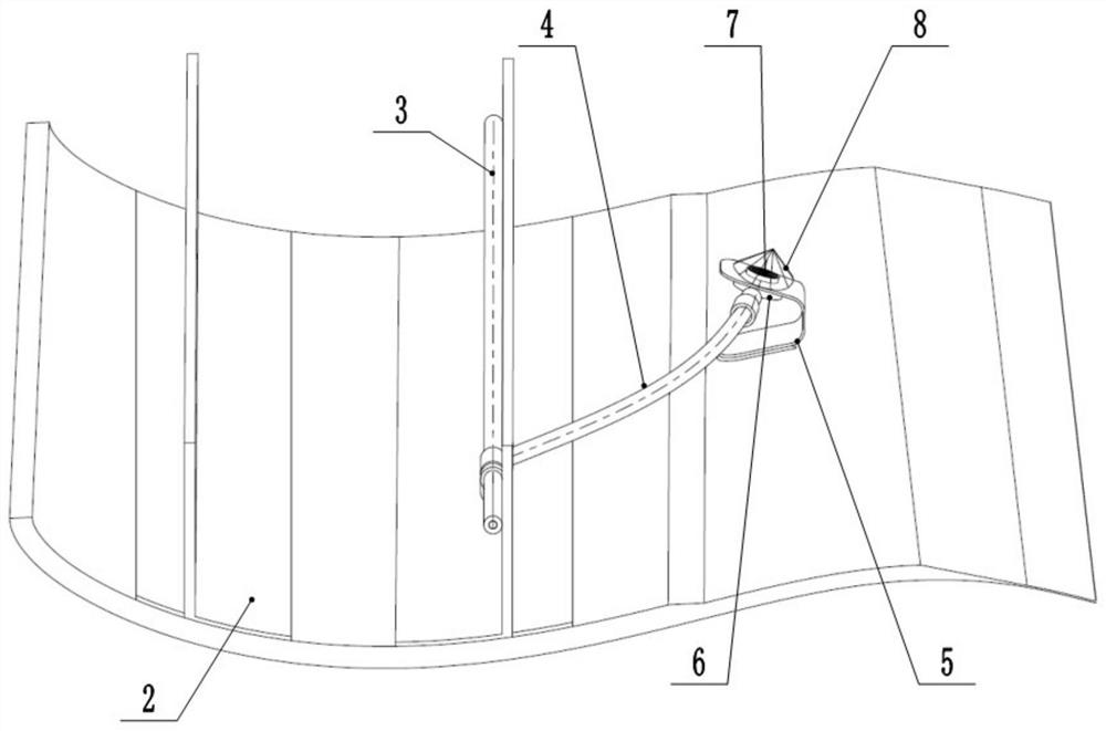
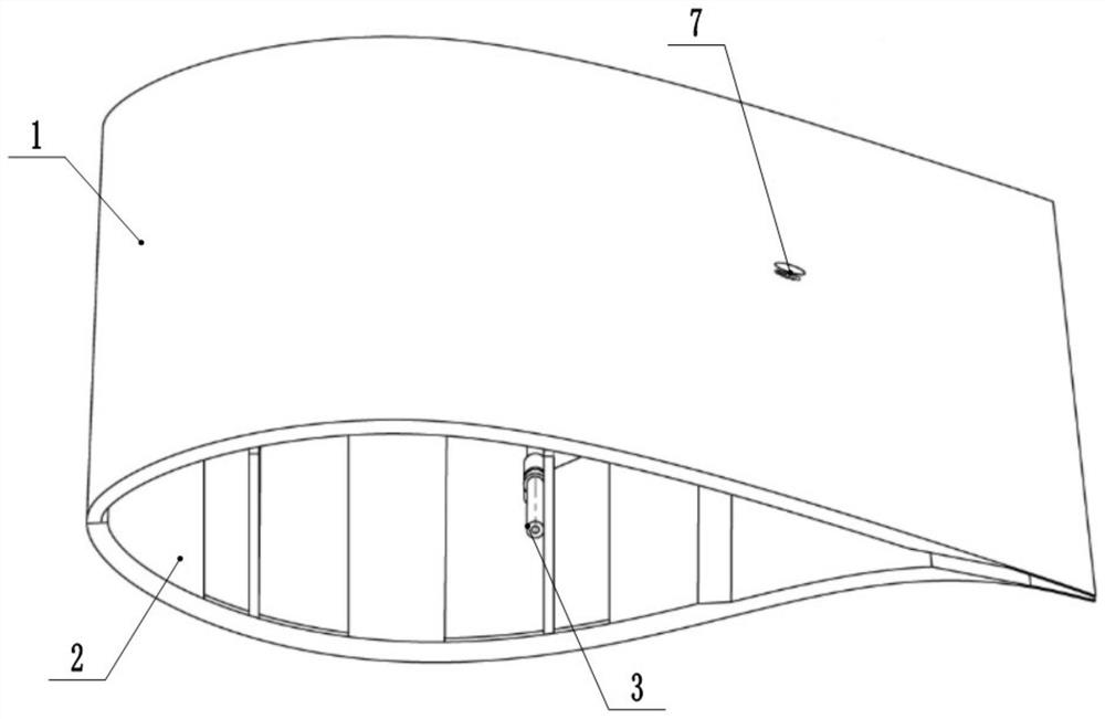
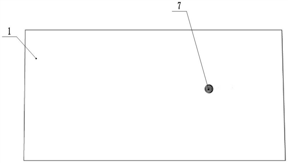
[0043] Basic as attached Figure 1-12 Shown: a wind power blade air-termination installation device, including the upper air-termination installation assembly and the lower air-termination installation assembly, the upper air-termination installation assembly installs the upper air-termination 14 on the upper housing 1 of the wind power blade; The air-termination installation assembly is used to install the lower air-termination device on the lower shell 2 of the wind turbine blade; the upper air-termination installation assembly includes a first positioning plug 7, an adhesive layer 8, a sealing layer, a C-shaped mounting pad 5, a guide Shaft 16, first hole opener 12 and second hole opener 13; C-type mounting pad 5 is an elastic pad, such as figure 1 , 6 , 7, one side of the C-type mounting pad 5 is fixed on the inner wall of the lower case 2, and the other side of the C-type mounting pad 5 is fixed on the base 6 of the lightning receptor 14. The base 6 of the upper air rec...

Embodiment 2

[0045] A method for installing a wind power blade lightning receptor, using the wind power blade lightning receptor installation device of Embodiment 1, comprising the following steps:

[0046] Step 1: Preparations before mold closing;

[0047] S1.1: Connect the base 6 of the upper air-termination device 14 to the sub-wire 4, tighten the first positioning plug 7 of the upper housing 1 on the base 6 of the upper air-termination device 14, and fix the C-shaped mounting pad 5 on the lower housing on the inner wall of the body 2; glue the base 6 of the upper lightning receptor 14 on the C-shaped mounting pad 5, and the first positioning plug 7 faces the inner wall of the upper housing 1; stick on the center hole 11 of the first positioning plug 7 One layer of sealing layer, an adhesive layer 8 is set around the base 6 and the first positioning plug 7 for wrapping, specifically, glue is accumulated on the base 6 and the first positioning plug 7, and the first positioning plug 7 is ...


PUM

PropertyMeasurementUnit
diameteraaaaaaaaaa
diameteraaaaaaaaaa

Abstract

The invention belongs to the technical field of wind power blades, and particularly discloses a wind power blade lightning arrester mounting device and a mounting method. The wind power blade lightning arrester mounting device comprises an upper lightning arrester mounting assembly and a lower lightning arrester mounting assembly, the upper lightning arrester mounting assembly comprises a first positioning plug, a bonding layer, a C-shaped mounting pad, a guide shaft, a first tapper and a second tapper, one side of the C-shaped mounting pad is fixed to the inner wall of a lower shell body, the other side of the C-shaped mounting pad is fixed to a base of an upper lightning arrester, an internal threaded hole matched with the upper lightning arrester is formed in the base of the upper lightning arrester in advance, the first positioning plug comprises a screw rod and a positioning block, the upper end face of the positioning block is provided with a center hole and a plurality of annular grooves, the lower part of the positioning block is integrated with the screw rod; the lower lightning arrester mounting assembly comprises a second positioning plug, and the guide shaft can be inserted into the center holes of the first positioning plug and the second positioning plug and is used for guiding the second tapper. By means of the wind power blade lightning arrester mounting device, the problem that in the prior art, drilling cannot be accurately conducted perpendicular to the base can be solved.

Description

technical field [0001] The invention belongs to the technical field of wind power blades, and in particular relates to a wind power blade lightning receptor installation device and an installation method. Background technique [0002] Wind power blades work in high-altitude or open environments such as mountains, coasts, and seas. They are the objects closest to the clouds on the ground, and are extremely vulnerable to lightning strikes during thunderstorms. The blade lightning receptor can guide the lightning directionally and conduct the lightning current. The installation quality of the air receptor directly affects the operation safety of the blades and maintenance personnel. The most ideal installation is that the air-terminating device is in surface-to-face contact with the base, so as to obtain sufficient diversion cross-sectional area, and at the same time provide a stable connection and stable electrical conductivity. [0003] At present, the blade lightning prote...

Claims


Application Information

Patent Timeline
Patent Type & Authority Applications(China)
IPC IPC(8): B23Q3/06B23B41/00B23P19/00
CPCB23B41/00B23P19/00B23Q3/06
Inventor 谢磊秦梓程王振刚汪建袁亚丽岳晓敏
Owner JILIN CHONGTONG CHENGFEI NEW MATERIAL
Why Eureka
Try Eureka