
Optical precision machining unit

A processing unit and optical precision technology, applied in stone processing equipment, optical surface grinders, stone processing tools, etc., can solve the problems of processing efficiency decline, achieve high processing accuracy and ensure symmetry

Pending Publication Date: 2021-06-11
苏州阿奎睿思机器人科技有限公司
View PDF0 Cites 0 Cited by
  • Summary
  • Abstract
  • Description
  • Claims
  • Application Information

AI Technical Summary

Problems solved by technology

Due to the complex shape of optical precision parts, the traditional optical precision machining unit will lead to a decrease in processing efficiency

Method used

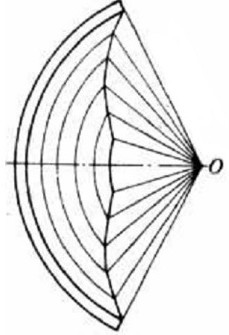
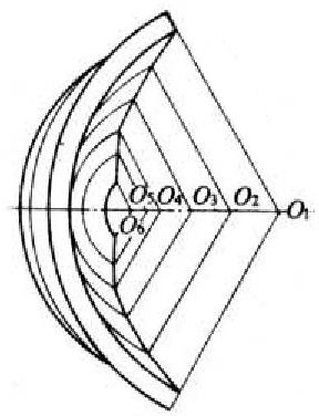

Image

  • Optical precision machining unit
  • Optical precision machining unit
  • Optical precision machining unit

Examples


Embodiment Construction

[0021] The preferred embodiments of the present invention are described in detail below, so that the advantages and features of the present invention can be more easily understood by those skilled in the art, so as to define the protection scope of the present invention more clearly.

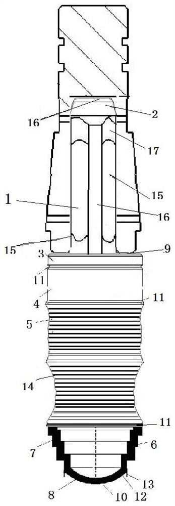
[0022] See attached figure 1 As shown, a kind of optical precision machining unit comprises a grinding tool holder, a grinding tool installed in the grinding tool fixing clamp hole 15 of the grinding tool base, and a control unit. The grinding tool base has a grinding tool fixing clamp hole 15, and the grinding tool is fixed The inner top of the clip hole 15 has a limiting surface 16 .

[0023] The grinding tool includes a handle 1, the upper end of the handle 1 has a tapered tool guide 2, the tool guide 2 is pressed against the limit surface 16 in the fixing clamp hole 15 of the grinding tool, the tool handle 1 includes a The plurality of first planes 15 made by extrusion molding method and th...


PUM


Abstract

The invention discloses an optical precision machining unit. The optical precision machining unit comprises a grinding tool base, a grinding tool installed in a grinding tool fixing clamping hole of the grinding tool base and a control unit, the grinding tool comprises a tool handle, and the lower end of the tool handle is coaxially provided with a polished rod section, an appearance roughing section, a first appearance finishing section, a second appearance finishing section, a punching finishing section and a punching cutting roughing section, and the control unit records height position information of the polish rod section, the appearance roughing section, the first appearance finishing section, the second appearance finishing section, the punching finishing section and the punching cutting roughing section and controls the grinding tool base to move in the vertical direction according to instructions. The optical precision machining unit has the advantages and beneficial effects that the corresponding tool structure layers are precisely defined in the axial direction, multiple machining functions are integrated on a tool, and extremely high machining precision is provided for the shape finishing section of a special structure.

Description

technical field [0001] The invention relates to an optical precision processing unit. Background technique [0002] In the grinding process of precision optical glass, due to the high requirements of precision optics for finishing, the existing processing equipment cannot meet the requirements. With the development of CNC machinery and equipment, the technical requirements for high-density, high-precision CNC machining equipment are getting higher and higher, and the efficiency and quality of CNC machining are directly related to the mold structure. Due to the complex shape of optical precision parts, the traditional optical precision machining unit will lead to a decrease in processing efficiency. Contents of the invention [0003] In order to overcome the deficiencies in the prior art, the purpose of the present invention is to provide a high-precision optical precision machining unit. [0004] To achieve the above object, the present invention provides an optical prec...

Claims


Application Information

Patent Timeline
Patent Type & Authority Applications(China)
IPC IPC(8): B24B13/01B24B9/14B28D1/14
CPCB24B13/01B24B9/14B24B9/146B28D1/146
Inventor 刘喜川
Owner 苏州阿奎睿思机器人科技有限公司
Learn More