Crossing type traction and insertion combining device for U-shaped pipe of cooling tower

A combined device and U-shaped tube technology, which is applied in the field of cooling towers, can solve problems such as tube plate misalignment, low U-shaped tube assembly efficiency, and U-shaped tube misalignment.

Active Publication Date: 2021-06-11
菏泽市花王科技工贸有限公司
View PDF6 Cites 0 Cited by
  • Summary
  • Abstract
  • Description
  • Claims
  • Application Information

AI Technical Summary

Problems solved by technology

[0005] In order to overcome the prior art in the process of assembling the U-shaped tubes of cooling towers, it is necessary to manually erect and fix multiple tube sheets, and then manually pass the U-shaped tubes through the holes of multiple tube sheets in turn. There is a certain distance between them, and the tube plate cannot ensure that the holes are completely aligned during the process of arranging and placing the tube plate, which leads to misalignment during the manual insertion of the U-shaped tube, and the U-shaped tube will be blocked during the insertion process. At this time, it is necessary to manually align and reinsert the pipe, and at the same time, the tube sheet is misaligned in some positions, and the tube sheet needs to be adjusted, resulting in the disadvantage of low assembly efficiency of the U-shaped tube. The technical problem to be solved is: to provide a U-shaped cooling tower. Pipe straddling pulling and plugging combination device

Method used


Image

  • Crossing type traction and insertion combining device for U-shaped pipe of cooling tower
  • Crossing type traction and insertion combining device for U-shaped pipe of cooling tower
  • Crossing type traction and insertion combining device for U-shaped pipe of cooling tower

Examples


Embodiment 1

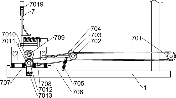
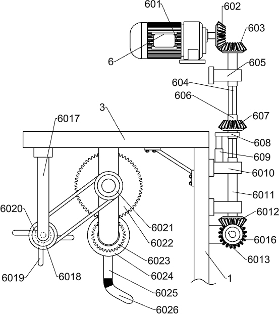
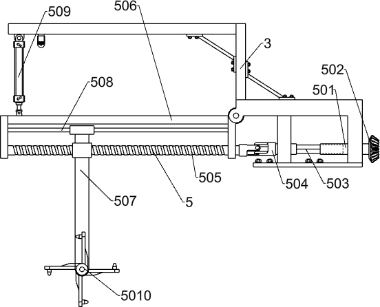
[0095] A cooling tower U-shaped pipe spanning type pulling combination device, such as Figure 1-9 As shown, it includes a body frame 1, a wheel 2, a top mounting frame 3, a push handle bar frame 4, a traction alignment system 5, an auxiliary propulsion system 6, a first fixed alignment system 7 and a second fixed alignment system 8 ; The top of the wheel 2 is bolted to the body frame 1; the bottom of the top mounting frame 3 is bolted to the body frame 1; Push the handlebar frame 4 to weld with the body frame 1; The auxiliary propulsion system 6 is connected with the top mounting frame 3, the auxiliary propulsion system 6 is connected with the vehicle body frame 1, and the auxiliary propulsion system 6 is connected with the traction alignment system 5; the first fixed alignment system 7 is connected with the vehicle body The frame 1 is connected, the first fixed positioning system 7 is connected with the auxiliary propulsion system 6; the second fixed positioning system 8 is ...


PUM


Abstract

The invention relates to the field of cooling towers, in particular to a crossing type traction and insertion combining device for a U-shaped pipe of a cooling tower. The invention aims to provide the crossing type traction and insertion combining device for the U-shaped pipe of the cooling tower. According to the technical scheme, the crossing type traction and insertion combining device for the U-shaped pipe of the cooling tower comprises a vehicle body frame, wheels, a top mounting frame, a pushing hand lever frame, a traction position correcting system and the like; the upper portions of the wheels are in bolted connection with the vehicle body frame, the lower portion of the top mounting frame is in bolted connection with the vehicle body frame, and the pushing hand lever frame is welded to the vehicle body frame; and the traction position correcting system is connected with the top mounting frame, and an auxiliary pushing system is arranged. According to the crossing type traction and insertion combining device for the U-shaped pipe of the cooling tower, automatic assembling of the U-shaped pipe of the cooling tower is achieved, it is guaranteed that the U-shaped pipe is accurately inserted into a hole of a pipe plate by pulling a pipe head to move in the process that the U-shaped pipe is inserted into the pipe plate, and meanwhile, the pipe plate is fixed and slightly vibrated, so that the U-shaped pipe is smoothly inserted into the pipe plate.

Description

technical field [0001] The invention relates to the field of cooling towers, in particular to a U-shaped pipe spanning type pulling and pulling combined device of cooling towers. Background technique [0002] The cooling tower is a device that uses water as a circulating coolant to absorb heat from a system and discharge it into the atmosphere to reduce the temperature of the water; its cooling is to use water and air to exchange heat and cold to generate steam, and the volatilization of the steam takes away the heat to achieve evaporation. The principle of heat dissipation, convective heat transfer and radiation heat transfer is to dissipate the waste heat generated in the industry or refrigeration and air conditioning to reduce the water temperature of the evaporative heat dissipation device to ensure the normal operation of the system. [0003] At present, in the prior art, in the process of assembling the U-shaped tubes of the cooling tower, it is necessary to manually e...

Claims


Application Information

Patent Timeline
Patent Type & Authority Applications(China)
IPC IPC(8): B25B27/14B25B11/02
CPCB25B27/14B25B11/02
Inventor 杨文开
Owner 菏泽市花王科技工贸有限公司
Why Eureka
Try Eureka