Thermal control method for aerospace equipment

A technology for aerospace equipment and thermal control, which is applied to the devices for controlling the living conditions of space vehicles, etc., can solve the problems of long time consumption, burnout of resistance elements, hindering the heat transfer relationship between the heater and the surface of the controlled object, etc., and achieve good filling. ability, saving curing time, and the effect of strong operability

Active Publication Date: 2021-06-11
航天科工空间工程发展有限公司
View PDF7 Cites 1 Cited by
  • Summary
  • Abstract
  • Description
  • Claims
  • Application Information

AI Technical Summary

Problems solved by technology

[0009] When heaters need to be implemented on multiple surfaces of the object to be controlled, multiple surfaces need to be pasted and cured by heaters in sequence, and the serial implementation process takes a long time;
[0010] From the implementation results, based on the currently commonly used heater paste process, the implementation effect is not stable, and the probability of large bubbles or many small bubbles appearing when the silicone rubber is cured is relatively high, which hinders the heater from connecting with the surface of the controlled object. In severe cases, the resistance element at the position of the bubble will be blown, thus making the active thermal control circuit invalid

Method used


Image

  • Thermal control method for aerospace equipment
  • Thermal control method for aerospace equipment
  • Thermal control method for aerospace equipment

Examples


Embodiment Construction

[0036] In order to make the technical solutions and advantages of the present invention clearer, the implementation manners of the present invention will be further described in detail below in conjunction with the accompanying drawings. Similar parts in the figures are denoted by the same reference numerals. Those skilled in the art should understand that the content specifically described below is illustrative rather than restrictive, and should not limit the protection scope of the present invention.

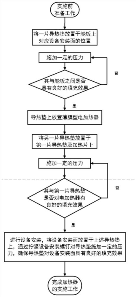
[0037] combine image 3 and Figure 4 A thermal control method for aerospace equipment according to an embodiment of the present invention is described. The methods include:

[0038] S100, disposing the first packing 5 on the deck 6 at a position corresponding to the installation surface of the aerospace equipment (that is, the controlled object) to be installed.

[0039] In a specific example, the first filler is a low interface thermal resistance filler, such as a therm...


PUM


Abstract

One embodiment of the invention discloses a thermal control method for aerospace equipment. The thermal control method comprises the steps that S100, arranging a first filler at the position, corresponding to the to-be-installed aerospace equipment, of a cabin plate of a spacecraft; S102, applying a pressure, so that air between the first filler and the deck is exhausted; S104, arranging a film type electric heater on the first filler; S106, arranging a second filler on the film type electric heater; S108, applying a pressure to discharge air among the first filler, the second filler and the film type electric heater; and S110, arranging the aerospace equipment to be installed on the second filler, and exhasuting air between the second filler and the equipment through pressing. The method has the following advantages that the implementation process of the electric heater and the installation process of equipment are synchronously carried out, a traditional gluing mode is not used, and the glue curing time is saved; the whole implementation process is extremely high in operability, and air on the contact interface of the heater and the filler can be effectively exhausted.

Description

technical field [0001] The invention relates to the field of implementing thermal control measures for aerospace equipment. More specifically, it relates to a thermal control method for aerospace equipment. Background technique [0002] At present, aerospace technology is an important means of quickly acquiring and transmitting information, and has a wide range of application requirements in military and commercial fields. The harsh operating environment puts forward high requirements on the adaptability of aircraft, aerospace equipment and loads to the space thermal environment. . In order to ensure that the temperature level and stability of the aircraft and its key equipment meet the normal working requirements, the design of the thermal control system becomes the key to the overall system design and development. Thermal control system design includes active thermal control design and passive thermal control design. Passive thermal control measures suppress or strengthe...

Claims


Application Information

Patent Timeline
Patent Type & Authority Applications(China)
IPC IPC(8): B64G1/50
CPCB64G1/50Y02T50/40
Inventor 隋愿愿赵益涛张楠李子轩李粲王珏段友东
Owner 航天科工空间工程发展有限公司
Why Eureka
Try Eureka