
Rainwater collecting device for building energy conservation

A rainwater collection device and building energy-saving technology, applied in drinking water devices, water supply devices, buildings, etc., can solve the problems of resource waste, water shortage, inapplicability, etc., and achieve the effect of improving efficiency and uniformity

Inactive Publication Date: 2021-06-11
张莹
View PDF0 Cites 0 Cited by
  • Summary
  • Abstract
  • Description
  • Claims
  • Application Information

AI Technical Summary

Problems solved by technology

[0002] At present, the water we rely on for survival is becoming increasingly scarce, and many people do not realize that, especially on construction sites, a large amount of water needs to be used to shower bricks, make concrete, etc., and these do not require particularly clean water, some rainwater It can also be used, but there is no device for collecting rainwater on the existing construction site, and a large amount of rainwater is directly drained, resulting in a waste of resources. Suitable for high standard construction water

Method used


Image

  • Rainwater collecting device for building energy conservation
  • Rainwater collecting device for building energy conservation
  • Rainwater collecting device for building energy conservation

Examples


Embodiment Construction

[0030] The following will clearly and completely describe the technical solutions in the embodiments of the present invention with reference to the accompanying drawings in the embodiments of the present invention. Obviously, the described embodiments are only some, not all, embodiments of the present invention. Based on the embodiments of the present invention, all other embodiments obtained by persons of ordinary skill in the art without making creative efforts belong to the protection scope of the present invention.

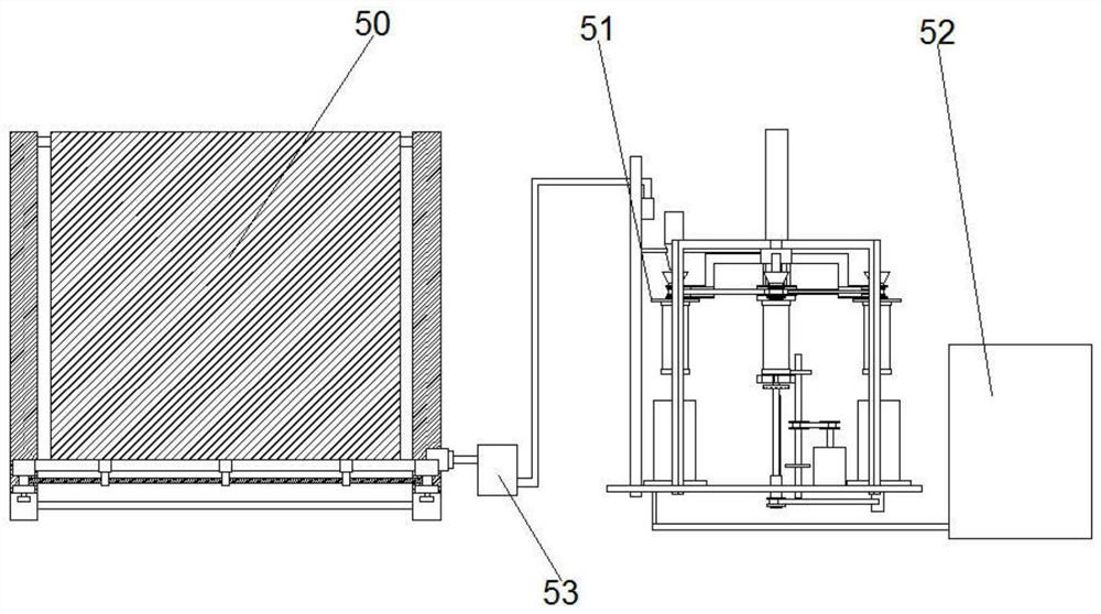
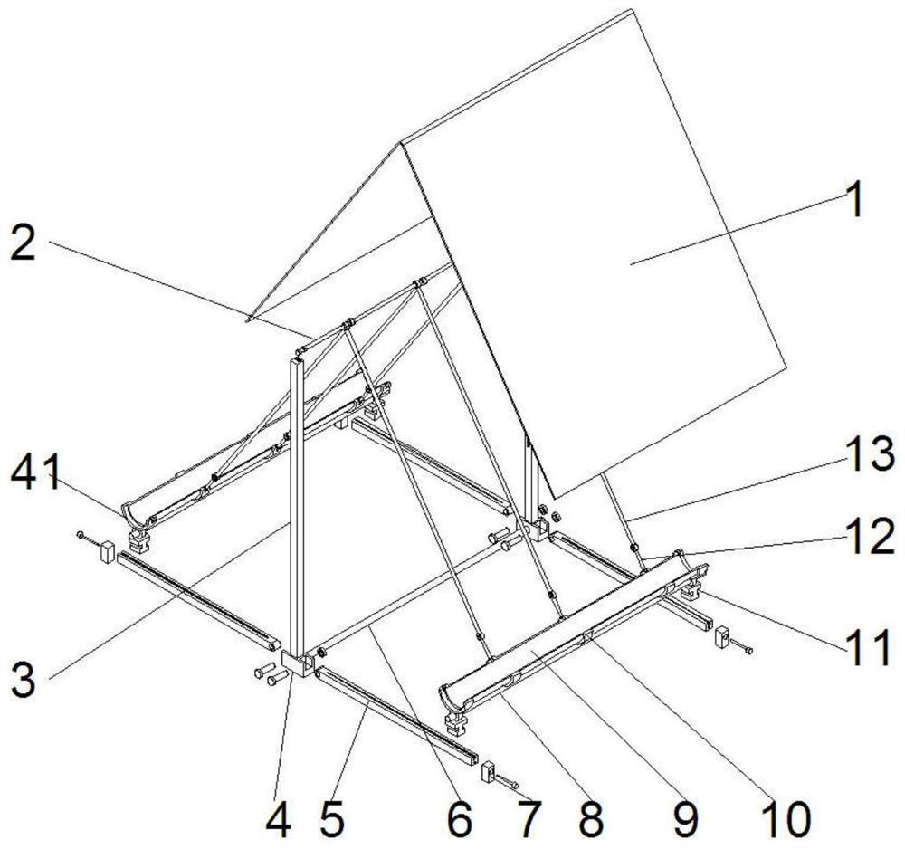
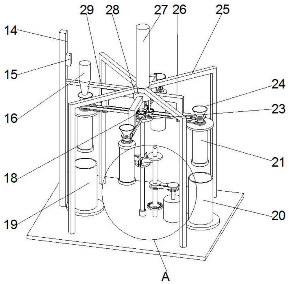
[0031] see Figure 1-8 , in an embodiment of the present invention, a rainwater collection device for energy saving in buildings includes a rainwater collection module 50, a rainwater filtration module 51, and a threaded telescopic hose 42, and the rainwater collection module 50 includes a waterproof cloth 1, an upper support rod 2, a support Column 3, water collection tank 9, support column 3 is symmetrically provided with two, and support column 3 side surfa...


PUM


Abstract

The invention discloses a rainwater collecting device for building energy conservation. The rainwater collecting device comprises a rainwater collecting module, a rainwater filtering module and a threaded telescopic hose, wherein the rainwater collecting module comprises waterproof cloth, an upper supporting rod, a supporting stand column and a water collecting tank; the rainwater filtering module comprises a telescopic driving device, a chain wheel transmission structure, a belt transmission structure I and a supporting plate; a filtering barrel and a cleaning barrel are symmetrically arranged on the left side and the right side of the upper surface of the supporting plate; the telescopic driving device is arranged at the upper end of a supporting frame; one end of a rotating arm is rotationally connected with a filter element; a driving rod is connected in a rotating bearing in a sliding mode; a bevel gear II, a bevel gear I and the chain wheel transmission structure are arranged at the upper part of the driving rod in a sleeving mode; and a servo motor and a rotating shaft rod are arranged on the upper surface of the supporting plate. The inclination angle of the waterproof cloth can be adjusted, the contact area between the waterproof cloth and rainwater is controlled, different precipitation amounts are adapted, filtering and cleaning of the filter element are synchronously carried out, the filter element is automatically cleaned, the rainwater filtering uniformity is improved, and the cleaning efficiency is synchronously improved.

Description

technical field [0001] The invention relates to the technical field of building energy saving, in particular to a rainwater collection device for building energy saving. Background technique [0002] At present, the water we rely on for survival is becoming increasingly scarce, and many people do not realize that, especially on construction sites, a large amount of water needs to be used to shower bricks, make concrete, etc., and these do not require particularly clean water, some rainwater It can also be used, but there is no device for collecting rainwater on the existing construction site, and a large amount of rainwater is directly drained, resulting in a waste of resources. Suitable for high standard construction water. Therefore, those skilled in the art provide a rainwater collection device for building energy saving to solve the problems raised in the background technology above. Contents of the invention [0003] The object of the present invention is to provide...

Claims


Application Information

Patent Timeline
Patent Type & Authority Applications(China)
IPC IPC(8): E03B3/02B01D29/35B01D29/50B01D35/12
CPCB01D29/35B01D29/50B01D35/12E03B3/02Y02A20/108
Inventor 张莹
Owner 张莹
Learn More